
Remove the front wheel, ABS wheel speed sensor and brake caliper and secure it with a wire clamp to the vehicle body.
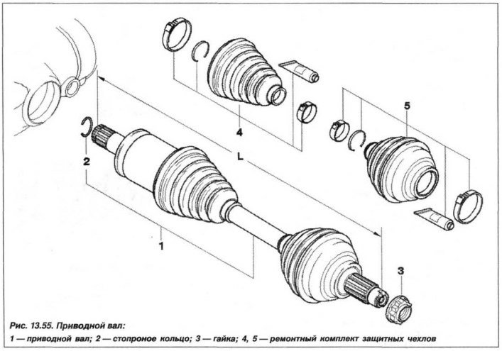
Disconnect the tie rod from the swivel head and the tie rod from the swivel bearing. Detach the front control arm from the swing arm. Loosen the collar nut securing the drive shaft to the swivel bearing.
Press the drive shaft out of the flange and move the swivel bearing aside, fix it with a wire clamp on the car body.
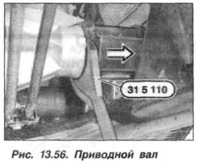
Using fixture «31.5.110» (pic. 13.56), press the wheel drive shaft out of the front axle reduction gear and remove it.
The installation of the drive shaft of the wheel should be carried out in the reverse order, while it is necessary.
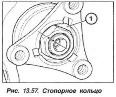
Replace seal and circlip (arrows, fig. 13.57) drive shaft. Install the drive shaft, overcoming the resistance of the retaining ring. The drive shaft should engage with an audible click.
Check the oil level in the front axle gearbox and install the stiffening plate.