
Examination
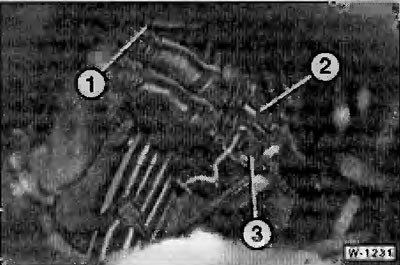
Location of connectors located under the intake manifold, viewed from the front:
- 1 - for knock sensor (closed);
- 2 - for the pulse sensor at the crankshaft;
- 3 - for cylinder identification sensor.
To check, disconnect the appropriate plug from the engine wiring harness. If necessary, you must first remove the intake manifold, because. plugs are difficult to access.
Using an ohmmeter, measure the resistance at the plug contacts of the respective sensor; replace the sensor if necessary.
Prescribed resistance value at +20°C:
- impulse sensor at the crankshaft: 1.3k Ω
- cylinder identification sensor: between pins 1 and 2: 1 sigma maximum; between pins 2 and 3: more than 10 M Ω.
Removing the pulse sensor from the crankshaft
Disconnect plug connector for pulse encoder.
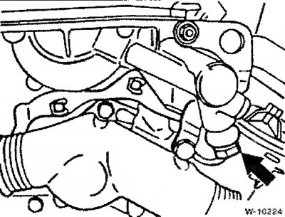
Unscrew the fastening of the oil line at the actuator of the VANOS system and plug the holes with clean plugs.
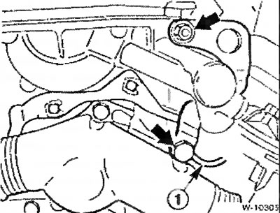
Unscrew the fastening of the eye for hanging the engine, at the same time note the position of the wire -1- for its subsequent installation.
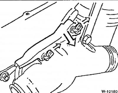
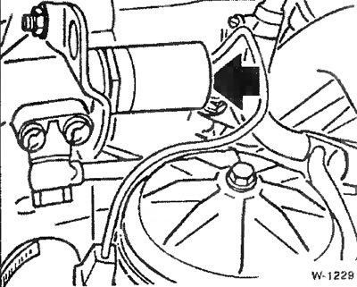
Pull the sensor wire out of the guides. To do this, detach from the clamps and remove the cable management box, see figure.
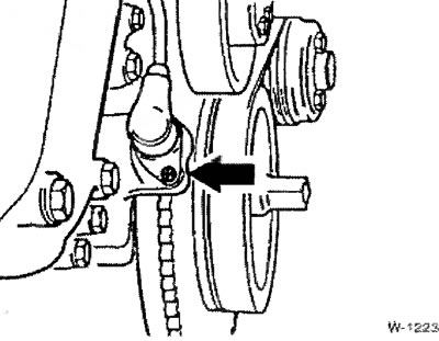
Loosen the fastening screw at the flywheel gear and remove the sensor together with the cover.
Installation
Insert the sensor and tighten the screw to 5 Nm, i.e. easy enough.
Check the gap between the sensor and the gear with a feeler gauge. The prescribed clearance value is 0.7-1.3 mm.
Place the connecting cable back into the guides so that it does not rub against the V-belt. Insert plug.
Removing the Cylinder ID Sensor
Remove the upper engine cover, see p. 42.
Access to the sensor is difficult. Therefore, the plug connection of the VANOS actuator solenoid valve must first be disconnected and the valve removed.
Unfasten the oil line at the VANOS actuator and plug the holes with clean plugs, see drawing W-10224.
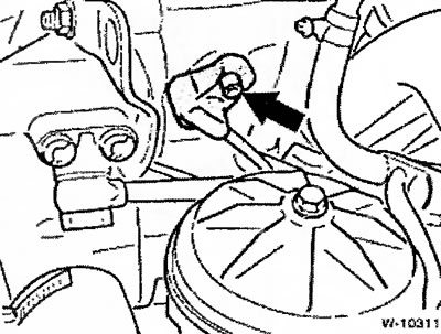
Loosen the fixing screw and remove the sensor.
Disconnect the sensor connector.
Installation
Insert sensor. Make sure that the rubber seal is in the correct position; if necessary, replace the seal.
Tighten the sensor mount to 5 Nm, i.e. easy enough.
Lay and connect pilot wire.
Fit new O-rings and tighten the VANOS actuator oil line to 30 Nm.
Screw the solenoid valve into the VANOS actuator and tighten to 30 Nm; if necessary, first replace the damaged seal. Connect the plug connector of the solenoid valve.
Install upper engine cover, see p. 42.