
Attention! Hydraulic tappets that have been in operation must be installed only in their original places.
All valve springs must be replaced in the following order. Prepare the tools "11.0.342", "11.0.345", "11.1.045", "11.1.065", "11.1.441", "11.3.030" and "11.3.250". Remove the cylinder head, having first secured the hydraulic tappets using the "11.3.250" tools (fig. 3.128) in the cylinder head.

Remove the mounting bar assembly together with the hydraulic tappets. When removing, fold the hydraulic tappets in strict sequence by cylinder numbers. Assemble the device "11.1.441", "11.1.065" and "11.1.045". Center the "11.0.345" tool relative to the valve axis by inserting it into the corresponding recess in the "11.0.342" tool (fig. 3.129).
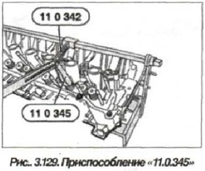
By pressing the device "11.0.345" on the upper plate (3, see Fig. 3.124) compress the valve spring (4) and remove the crackers (6).
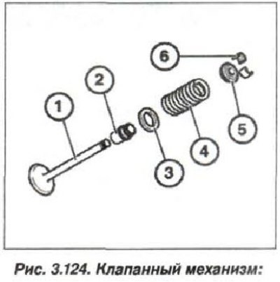
1 - valve; 2 - oil seal; 3 - lower spring plate; 4 - valve spring; 5 - upper spring plate; 6 - crackers
Gently release the lever, remove the plate and take out the valve spring with the lower plate.