
Attention! The sequence of operations for removing and installing the actuator unit of the D-VANOS system is different.
The VANOS actuator unit must be removed in the following order. Prepare the tools "00.9.250", "11.2.300", "11.3.240", "11.3.450", "11.4.220" and "11.6.170" and remove the engine soundproofing casing. Remove the air filter housing together with the air flow meter.
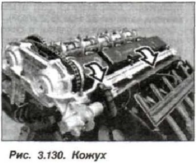
Remove the fan impeller with the viscous fan drive coupling and the fan casing. Remove the cylinder head cover. Unscrew all spark plugs. Remove the plastic casing (fig. 3.130) the camshaft of the intake valves.
Disconnect the pressure oil line (30, see Fig. 3.63).
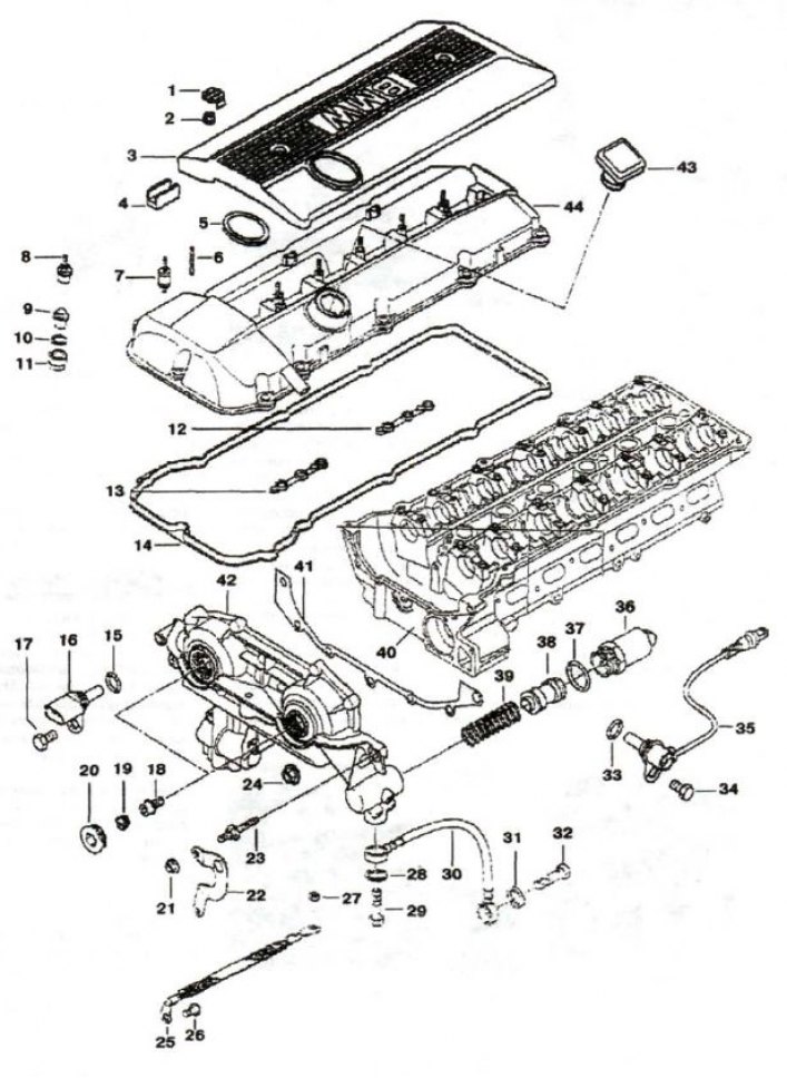
1, 19 - plug; 2 - nut; 3 - protective cover; 4 - overlay; 5, 28, 31, 33, 39 - sealing ring; 6, 23 - mounting pin; 7 - rubber-metal hinge; 8, 9 - cap nut; 10 - spacer washer; 11 - seal; 12, 13, 14 - profile gasket; 15, 37 - sealing ring (17x3); 16, 35 - camshaft sensor; 17, 34 - bolt (M6x16); 18 - precision bolt; 20 - plug with sealing ring; 21 - flange hook; 22 - fastening; 24 - nut M6; 25 - "mass" jumper; 26 - bolt (M6x10); 27 - nut M8; 29, 32 - hollow bolt; 30 - oil pipeline; 36 - EMC; 37 - ring (17x3); 38 - piston; 39 - spring; 40 - cylinder head; 41 - metal seal; 42 - actuator unit; 43 - oil filler cap; 44 - head cover
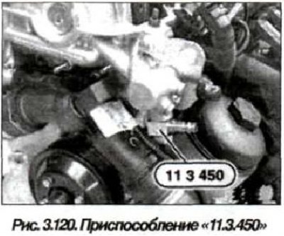
Install the device "11.3.450" (see fig. 3.120) with a hollow bolt of the pressure oil line.

Caution! Cover the actuator of the D-VANOS system, as a jet of oil will spray out of the hole when compressed air is supplied.
Connect a compressed air source (2-8 bar) to the "11.3.450" device.

Turn the engine crankshaft by the central bolt in the direction of rotation until the piston of the first cylinder reaches TDC of the compression stroke (fig. 3.106), while the air pressure is supplied.
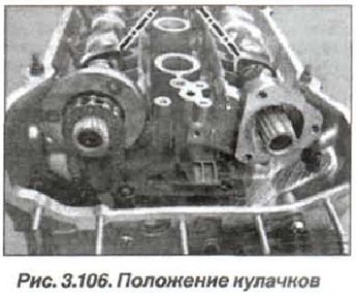
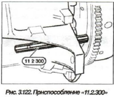
The tops of the camshafts of the first cylinder must be facing each other (see fig. 3. 106). Remove the plug from the hole for fixing the flywheel and lock the crankshaft at TDC at the end of the compression stroke of the 1st cylinder, using the device "11.2.300" (see fig. 3.122).

Attention! After finishing the work and before turning the engine shaft, do not forget to unlock the crankshaft, remove the device "11.2.300".
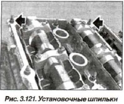
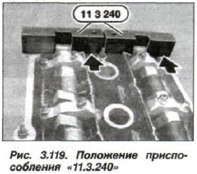
Remove the mounting studs (see fig. 3.121) and install the "11.3.240" device on the camshafts in the area of the 6th cylinder (see fig. 3.119).

Disconnect the compressed air source by closing the valve and removing the hose. Do not remove the "11.3.450" device yet.
Attention! After unscrewing the threaded plugs, oil flows out of the holes of the actuator unit of the system. Prevent oil from getting on the engine components.
Prepare rags and a container to collect the oil. Remove the plugs (20, see Fig. 3.63) using the device "11.6.170" or use needle-nose pliers.
Loosen the left-hand threaded bolts (18) on the inlet side and outlet side and collect the leaking oil.
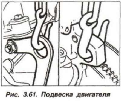
Disconnect the camshaft position sensor (35) and the electromagnetic valve (36) on the exhaust and intake sides. Loosen the bolts (see fig. 3.61) and remove the engine lifting eye.
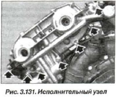
Unscrew the nuts (7 pcs., arrows, Fig. 3.131) and remove the actuator unit of the DVANOS system.
Attention! When the D-VANOS actuator is removed, it is strictly forbidden to rotate the engine shaft due to the possibility of engine failure when the valves and piston come into contact.
The installation of the D-VANOS actuator must be carried out in the following order. Check the centering bushings (2 and 7. see Fig. 3.4) for the absence of damage and correct installation.
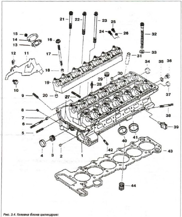
1 - cylinder head; 2.7 - centering sleeve; 3.8 - threaded plug (M8x1); 4 - cover (∅ 28); 5 - stud (M6x30); 6 - stud (M6x60); 9 - stud (M6x28); 10 - bolt (M8x28); 11 - harness holder; 12 - spacer; 13 - seal; 14.30 - lid; 15 - self-locking nut.; 16 - nut (M7); 17 - stud (M7x95); 18, 20 - center, bushing (∅ 9.5); 19 - support bar; 21 - bolt T (M6x50); 22 - bolt T (M6x70); 23 - bolt 7 (M6x100); 24 - threaded plug with sealing ring (M12x1.5x26); 25 - bolt; 26.35 - sealing ring; 27 - stud (M7x39); 28 - hairpin (M7/6x29.5); 29 - threaded plug (M18x1.5); 31 - guide bushing; 32 - head bolt (M10x110); 33 - spacer washer; 34 - cover (∅ 22); 36 - threaded plug (M10x1.0); 37 - cover (∅ 18); 38 - stud (M7x55); 39 - sensor; 40 - exhaust valve seat; 41 - valve seat; 42 - stud (M6x25); 43 - sealing gasket; 44 - check valve
The surfaces to be sealed must be clean and dry from dirt and traces of oil. Use a hardwood scraper and hydrolytic alcohol for cleaning. Apply a thin layer of sealant such as Drei Bond 1209 evenly to the corner joints of the end plane of the cylinder head connector with the actuator unit of the D-VANOS system.
Replace the sealing gasket. Install the D-VANOS actuator and secure it with bolts (arrows, Fig. 3.131).

Connect the camshaft position sensor SS and the solenoid valve SS on the exhaust and intake sides.
Insert and tighten the left-hand threaded precision bolts (18, 2 pcs., see fig. 3.63) piston fastenings to the splined shaft on the intake side and the exhaust side.
Tighten the bolt (M6) to a torque of 10 N·m (1.0 kgf·m). Install new plugs (19, see Fig. 3.63) using the "11.6.170" tool or use needle-nose pliers. Insert the threaded plugs (M22x1.5) with new sealing rings (20) and tighten them to a torque of 50 N·m (5.0 kgf·m). Install the engine lifting eye and tighten its mounting bolts.
Note: After replacing the actuator, it is necessary to check the valve timing and, if necessary, adjust them.
Remove the chain tensioner plunger cylinder (1, see Fig. 3.123), which is under spring pressure and remove it.
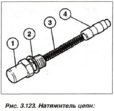
1 - cylinder; 2 - sealing ring; 3 - spring; 4 - plunger
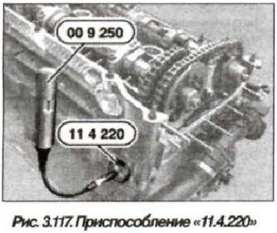
Install the device "11.4.220" (see fig. 3.117) into the hole on the cylinder head and turning the adjusting screw only bring it to the chain tensioner bar.

Pre-tension the tensioner bar using the "11.4.220" tool, screwing in the adjusting bolt using the "00.9.250" tool or a regular torque wrench, applying a torque of 0.7 N·m (0.07 kgf·m).
Pull back the device "11.2.300" (see fig. 3.122), to unlock the flywheel.

Remove the device "11.3.240" (see fig. 3.119).

Caution! Cover the actuator unit of the "D-VANOS" system when supplying compressed air from the opening.
Connect a source of compressed air (2-8 bar) to the device "11.3.450" (see 3.120).
Turn the engine shaft twice (by 720°) in the direction of rotation with compressed air supplied so that the tops of the camshafts of the intake and exhaust valves of the first cylinder are facing each other symmetrically "11.3.240" (see fig. 3.106).

Install the "112.300" device (see fig. 3.122) and lock the crankshaft in the TDC position of the compression stroke of the 1st cylinder.

Check the camshaft adjustment by installing the "11.3240" device (see fig. 3.119) on the camshafts.

Despite the correct adjustment of the camshafts, the "11.3.240" tool may protrude up to 1 mm relative to the intake side due to the tolerances of the D-VANOS system and the clearance in the gear engagement. The "11.2.240" tool must not protrude relative to the exhaust side, in which case the valve timing must be readjusted. Disconnect the compressed air source and remove the "11.3.450" tool (see fig. 3.120).

Connect the pressure oil line (30. see fig. 3.63) with new sealing rings (28), screwing in a hollow bolt M14x1.5 (29) with a tightening torque of 32 N·m (3.2 kgf·m).
Loosen the tension of the bar and remove the device "11.4.220" (see fig. 3.117).
Replace the sealing ring (2, see Fig. 3.123) and install the timing chain tensioner plunger cylinder.

1 - cylinder; 2 - sealing ring; 3 - spring; 4 - plunger
Tighten the cylinder nut (M26x1.5) to a torque of 70 N·m (7.0 kgf·m).
Remove the device "11.3.240" (see fig. 3.119).
Remove the device "11.2.300" (see fig. 3.122) and install the dust plug into the fixing hole.
Assemble the engine and check the crankshaft locking.
[Information taken from this resource bmwman.ru]