
Table of contents: Examination ↓ Replacement ↓
- Home
- BMW 5 Series
- E28
- Power unit
- Ignition system
- Checking and replacing the pulse sensor and ignition control unit (TCI system)
Checking and replacing the pulse sensor and ignition control unit (TCI system) (BMW 5 Series E28)
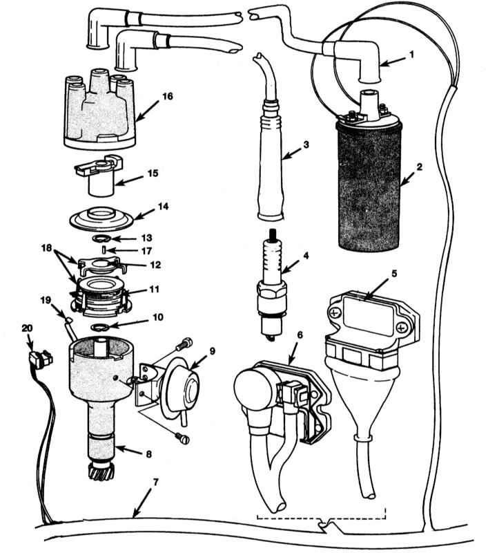
Schematic representation of ignition components of engines with TCI system
1 - High voltage wire of ignition coil
2 - Ignition coil
3 - Spark plug high voltage wire
4 - Spark plug
5 — Ignition control unit (Bosch)
6 — Ignition control unit (Siemens/ Telefunken)
7 — Cable
8 — Distributor body with centrifugal regulator with weights
9 - Vacuum diaphragm
10 — Retaining ring
11 — Pulse sensor
12 — Sensor rotor
13 — Retaining ring
14 - Dust cover
15 - Runner
16 — Distributor
17 - Cylindrical pin
18 — Rotor and projections of the pulse sensor
19 — Lid clamp
20 — Pulse sensor connector
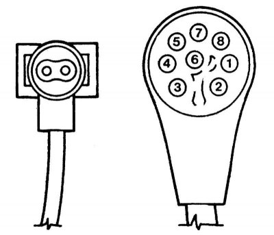
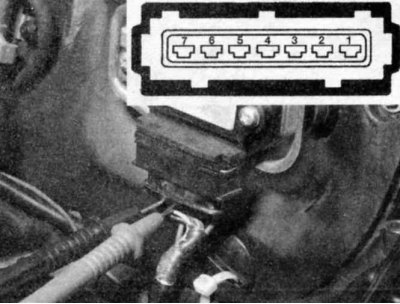
Pulse sensor (located in the ignition distributor) and the ignition coil needs to be checked if the spark plugs do not spark. Make sure the spark plug wires, coil, and spark plugs are in good condition (see sections Checking and replacing the ignition coil and Checking and replacing ignition sensors (motronic system)). There are two types of control units: Bosch and Siemens/Telefunken. Both types can be distinguished by their electrical connectors. The Bosch unit has one large rectangular connector at the bottom, while the Siemens/Telefunken unit uses two round electrical connectors at the front.
Examination
Power supply and grounding of the ignition control unit
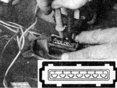
1. With the ignition off, disconnect the cable connectors from the ignition control unit. Connect a voltmeter between contacts 2 and 4 of the Bosch system connector or between contacts 6 and 3 of the Siemens/Telefunken system.
2. Turn on the ignition. Voltage should appear on the specified contacts. If there is no voltage, check the wires for breaks (see chapter On-board electrical equipment system).
3. Use an ohmmeter to check for a connection between pin 2 of the connector (Bosch) or pin 6 (Siemens/Telefunken) and the car body. There should be a short circuit.
4. Use an ohmmeter to check for a connection between pin 4 of the connector (Bosch) or pin 3 (Siemens/Telefunken) and contact 15 of the ignition coil. There should be a short circuit.
5. If the readings are incorrect, repair the cable.
Pulse sensor signal
1. If voltage is supplied to the ignition control unit, check the transmission of alternating voltage pulses from the sensor to the control unit.
2. Use a digital voltmeter for the following tests:
- On Bosch systems, connect the positive probe to pin 5 of the connector and the negative probe to pin 6.
- For Siemens/Telefunken systems, connect the positive probe to the () terminal of the small connector and the negative probe to the (-) terminal.
3. Have an assistant turn the engine over with the starter and check for an alternating voltage of 1 to 2 volts. If there is no voltage, check the cable between the pulse sensor (in the ignition distributor) and the control unit. If the cable is OK, check the resistance of the pulse sensor.
Do not operate the starter for a long time. If necessary, disconnect the cold start injector electrical connector to stop fuel supply to the engine.
4. To check the resistance of the pulse sensor, proceed as follows:
- In Bosch units, measure the resistance between contacts 5 and 6. The reading should be between 1000 and 1200 Ohms.
- In Siemens units, measure the resistance between the contacts of the smaller connector. The reading should be between 1000 and 1200 Ohms.
5. If the readings are incorrect, replace the pulse sensor. If the resistance values for the pulse sensor are correct and the voltages of the control units are (supply voltage and signal voltage) incorrect, replace the control unit.
Replacement
Ignition control unit
1. Make sure the ignition is off.
2. Disconnect the electrical connector(s) from the control unit.
3. Loosen the screws securing the control unit and remove it from the engine compartment.
4. Installation is the reverse of removal.
In Bosch control units, a special dielectric paste is installed between the rear part of the control unit and the heat radiator. In case of their separation (replacement or check) the old paste should be removed and the heat sink cleaned with 180 grit sandpaper. Apply Curil K2 paste (Bosch number 81229243). Instead of paste, you can use silicone dielectric compound. This treatment is very important to ensure a long service life of these expensive ignition components.
Pulse sensor
If your vehicle's radio is equipped with an anti-theft system, make sure you know the correct activation code before disconnecting the battery. Before disconnecting the wire, refer to Section Anti-theft audio system and instrument cluster language.
If a message in another language appears on the instrument cluster display after connecting the battery, refer to Section 1 for the language setting procedure Anti-theft audio system and instrument cluster language.
1. Disconnect the negative battery cable.
2. Remove the ignition distributor from the engine (see section Removal and installation the ignition distributor).
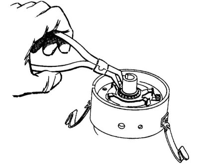
3. Using snap ring pliers, remove the snap ring holding the sensor rotor.
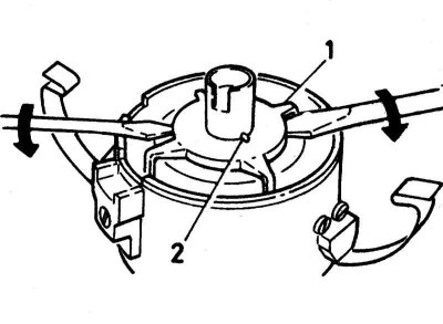
4. Using two flat-head screwdrivers on opposite sides, pry the sensor rotor and carefully lift it upwards.
Insert the screwdrivers as deep as possible without bending the sensor rotor. Only act on the strongest central part of the sensor rotor. If the sensor rotor is bent, it must be replaced.
Make sure that when removing the sensor rotor, the cylindrical pin does not fall out.
5. Remove the mounting screws, vacuum diaphragm and base from the pulse sensor electrical connector.
6. Unscrew the two screws of the vacuum corrector and separate it from the distributor by sliding it down and unhooking it from the base pin.
7. Using snap ring pliers, remove the snap ring holding the pulse sensor and base.
8. Carefully remove the pulse sensor together with the base.
9. Remove the three screws and separate the base from the pulse sensor.
10. Installation is the reverse of removal.
Remember to install the isolator ring between the sensor coil and the base. It must be centered before tightening the mounting screws. It will also be necessary to check/adjust the air gap if the sensor rotor has been removed or if you encounter an incorrect gap situation (see section Checking and adjusting the air gap (tCI system)).
(The original source of the article is on the website: BMWman.ru)
This article is available at russian, bulgarian, belarusian, ukrainian, serbian, croatian, romanian, polish, slovak, hungarian
Article verified: Zhuravleva Isolda
Share information:
Previous articles
БМВ E28: Ignition system
Next articles
Similar articles on other types of BMW cars:
Checking and replacing the pulse generator of the ignition… BMW 3 Series E21 (1975-1983)
Checking and replacing the pulse sensor BMW 3 Series E36 (1990-2000)
Replacing the EDC control unit BMW 7 Series E38 (1994-2001)
Pulse Generator — Checking and Replacing BMW 7 Series E32 (1986-1994)
Replacing the drive/control electronics compartment of the adaptive… BMW X3 E83 (2003-2010)
Replacing the actuator unit of the D-VANOS system BMW X5 E53 (1999-2006)
Link in different formats to this page
Visitor comments
No comments yet
- General information
- Governing bodies
- Manual
- Maintenance
- Power unit
- Engine repair
- Lubrication system
- Cooling system
- Ignition system
- Supply system
- Injection system (gasoline)
- Injection system (diesel)
- Exhaust system
- Transmission
- Clutch
- Car gearbox
- Front axle
- Rear axle
- Chassis
- Steering
- Brake system
- Wheels and tires
- Body
- Interior
- Exterior
- Heating system
- Electrical equipment
- Equipment and devices
- Power devices
- Windscreen wipers
- Electrical circuits
- General information
- Manual
- Maintenance
- Power unit
- Engine repair
- Ignition system
- Engine lubrication system
- Cooling system
- Fuel system (gasoline)
- Fuel system (diesel)
- Exhaust system
- Transmission
- Clutch
- Car gearbox
- Chassis
- Front and rear suspension
- Steering
- Brake system
- Body
- Exterior
- Interior
- Electrical equipment
- Heating system
- Equipment and devices
- Power devices
- Electrical circuits
- General information
- Manual
- Maintenance
- Power unit
- Engine in a car
- Engine overhaul
- Cooling system
- Supply system
- Ignition system
- Control system
- Transmission
- Clutch
- Manual gearbox
- Automatic gearbox
- Transmission line
- Chassis
- Steering
- Front suspension
- Rear suspension
- Brake system
- Body
- Body elements
- Car care and painting
- Electrical equipment
- Heater and air conditioner
- Equipment and devices
- Starter and generator
- Electrical circuits
- General information
- Operation and maintenance
- Specifications
- Power unit
- Engine repair
- Cooling and lubrication system
- Supply system
- Ecotronic power supply system
- Fuel injection system
- Ignition system
- Transmission
- Clutch
- Gearbox BMW 242/4
- Gearbox Getrag 262/8
- Gearbox Getrag 265/6
- Automatic gearbox
- Cardan gear
- Rear axle
- Chassis
- Steering
- Front suspension
- Rear suspension
- Brake system
- Electrical equipment
- Equipment and devices
- Electrical circuits