
Attention! During the work, do not allow the engine shaft to turn in the opposite direction (counterclockwise).
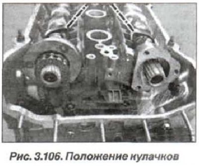
The valve timing adjustment of the engine camshafts must be carried out in the following order. Prepare the tools "00.9.250", "11.2.300", "11.3.240", "11.3.244", "11.3.292", "11.4.220" and "11.6.150". Set the crankshaft to the TDC position of the end of the compression stroke of the first cylinder. In this case, the tops of the camshaft cams should be facing each other (dash-dotted lines, see Fig. 3.106).
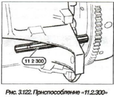
Lock the crankshaft with the device "11.2.300" (see fig. 3.122), which must be removed before rotating the engine shaft or starting it.

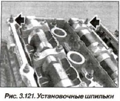
Remove the mounting studs (arrows, see Fig. 3.121) and remove the Q-VANOS system actuator.
Press the upper tensioner (14, see Fig. 3.15) secondary circuit down and lock it using the device "11.3.292".
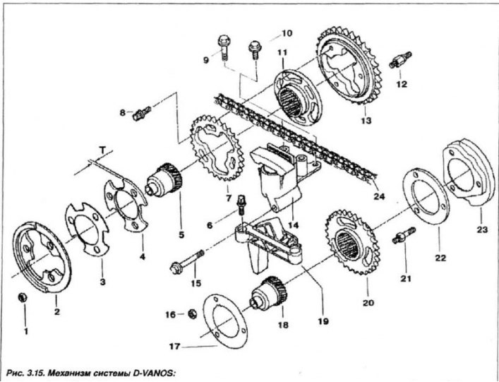
1, 16 - nut (M6); 2.23 - pulse sensor wheel; 3 - disc spring; 4 - thrust disc; 5.18 spline shaft; 6 - bolt T (M6x20); 7,13,20 - asterisk; 8 - bolt T (M7x18); 9 - bolt (M6x40); 10 - bolt (M6x16); 11 - toothed sleeve; 12.21 - pin; 14 - tensioner; 15 - bolt (M6x55); 17 - washer; 19 - guide; 22 - thrust disc
Unscrew the cylinder (1, see Fig. 3.123) and remove the timing chain tensioner plunger cylinder, taking into account that the piston cylinder is under significant pressure from the spring (3).
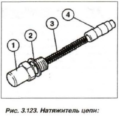
1 - cylinder; 2 - sealing ring; 3 - spring; 4 - plunger
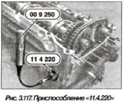
Insert the device "11.4.220" (see fig. 3.117) and install the adjusting screw tightly against the tensioner bar.

Loosen the bolts (3 pcs., 8, see fig. 3.15) half a turn. Loosen the nuts (1, 3 pcs.) by two turns, and the nuts (16, 3 pcs., 3) one turn.
Attention! The spline shaft (5, 18) slips very easily on the gear engagement.
Carefully pull out the splined shaft (18) of the intake camshaft until approximately 1 mm of the toothed ring is visible from the outside. Carefully pull out the splined shaft (5, see Fig. 3.15) exhaust camshaft to the stop.
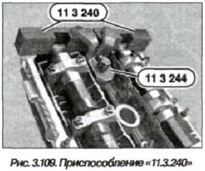
Install the "11.3.244" device onto the "11.3.240" device and secure them with a bolt screwed into the threaded hole of the spark plug (see fig. 3.109).
Press the upper tensioner of the secondary chain down and remove the device "11.3.292".
Pre-tension the tensioner bar using the tool "11.4.220" by screwing in the adjusting bolt using the tool "00.9.250" (see fig. 3.117) or with a conventional torque wrench, applying a torque of 0.7 N·m (0.07 kgf·m).
Press the wheel (2, see Fig. 3.15) camshaft position sensor, create a slight tension on the disc spring (3) and tighten the nuts (1, 3 pcs.) only by hand.
Remove the seal, clean and degrease the sealing surface of the cylinder head end. Check the centering bushings (2 and 7, see Fig. 3.4) for absence of damage and correct installation.
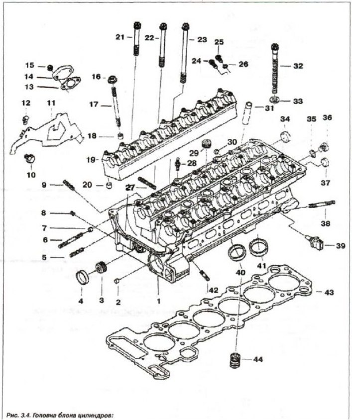
1 - cylinder head; 2.7 - centering sleeve; 3.8 - threaded plug (M8x1); 4 - cover (∅ 28); 5 - stud (M6x30); 6 - stud (M6x60); 9 - stud (M6x28); 10 - bolt (M8x28); 11 - harness holder; 12 - spacer; 13 - seal; 14.30 - lid; 15 - self-locking nut.; 16 - nut (M7); 17 - stud (M7x95); 18, 20 - center, bushing (∅ 9.5); 19 - support bar; 21 - bolt T (M6x50); 22 - bolt T (M6x70); 23 - bolt 7 (M6x100); 24 - threaded plug with sealing ring (M12x1.5x26); 25 - bolt; 26.35 - sealing ring; 27 - stud (M7x39); 28 - hairpin (M7/6x29.5); 29 - threaded plug (M18x1.5); 31 - guide bushing; 32 - head bolt (M10x110); 33 - spacer washer; 34 - cover (∅ 22); 36 - threaded plug (M10x1.0); 37 - cover (∅ 18); 38 - stud (M7x55); 39 - sensor; 40 - exhaust valve seat; 41 - valve seat; 42 - stud (M6x25); 43 - sealing gasket; 44 - check valve
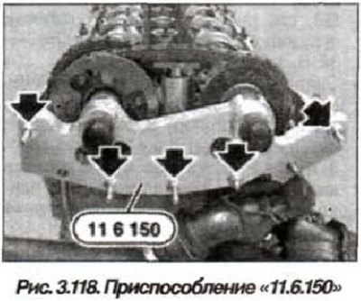
Install the device "11.6.150" (see fig. 3.118) only on a clean surface and tighten the nuts (arrows) by hand.

Tighten the mounting nuts evenly so that the device fits tightly to the cylinder head over the entire surface. Screw in the bolts (8, 3 pcs., see Fig. 3.15) on the outlet side and tighten them to a torque of 5.0 N·m (0.5 kgf·m) until they fit snugly.
Tighten the nuts (1, 3 pcs.) on the exhaust side and the nuts (16, 3 pcs.) on the intake side and tighten them to a torque of 5.0 N·m (0.5 kgf·m) until they fit snugly. Tighten the bolts (8, 3 pcs.) on the exhaust side, initially to a torque of 5.0 N·m (0.05 kgf·m), and then tighten them further to a torque of 20 N·m (2.0 kgf·m). Tighten the nuts (1, 3 pcs.) on the exhaust side and the nuts (16, 3 pcs.) on the intake side to a torque of 10 N·m (1.0 kgf·m).
Pull the "11.2.300" tool back enough to release (unlock) flywheel. Remove tools "11.3.244" and "11.3.240" (see fig. 3.109).

Turn the crankshaft two full turns clockwise (720°) and check the position of the camshaft lobes of the first cylinder (dashed line, see Fig. 3.106), they should be facing each other.

Install the device "11.2.300" (fig. 3.122), to lock the flywheel in the TDC position of the piston of the first cylinder at the end of the compression stroke.
Caution! Do not allow the engine to turn in the opposite direction. Before turning and starting the engine, remove the device "11.2.300".
Install the "11.3.240" tool on the camshafts (see fig. 3.119).
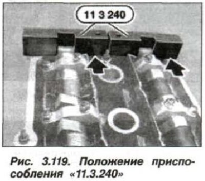
Despite the correct adjustment of the camshafts, the "11.3.240" device (arrows) may protrude by up to 1 mm relative to the intake side due to manufacturing tolerances of the D-VANOS system components and the clearance in the gear engagement. The "11.3.240" device must not protrude relative to the exhaust side, in which case the valve timing must be readjusted.
Loosen the chain tension and remove the tool "11.4.220" (see fig. 3.117).

Install the chain tensioner plunger cylinder (see fig. 3.123).

1 - cylinder; 2 - sealing ring; 3 - spring; 4 - plunger
Remove the device "11.2.300" (see fig. 3.122), to unlock the flywheel.
Remove the device "11.6.150" (see fig. 3.118).
Install the D-VANOS actuator. Install the previously removed components in the engine compartment. Check and restore the coolant and oil levels. Start the engine and check the tightness of the connections, the oil and coolant levels, and take a test drive.
(The article was copied from an online resource: BMWman)