
Attention! Pistons and piston pins are matched as a pair and cannot be disassembled.
The crankshaft connecting rod bearing cap is machined together with the connecting rod and cannot be disassembled. There is a marking by cylinder and direction.
The markings on the connecting rod and bearing cap must be on the same side and match.
When assembling, install the pistons, connecting rods and bearing shells in the same place and in the same position.
When installing pistons into cylinders, to avoid breaking piston rings, do not apply significant force.
The piston pin should be pushed through the bushing by pressing with a finger and should have no visible gap with it.
The pistons must be replaced in the following order. Prepare the tools "00.9.120", "11.2.110", "11.2.260", "11.2.470" and "11.3.480". Remove the engine, cylinder head, oil pan, oil pump and oil level stabilizer. Loosen the bolts and remove the piston cooling nozzles. Before removing the pistons, if there is a lot of oil carbon deposits, remove the oil film from the cylinder walls in the fire belt area.
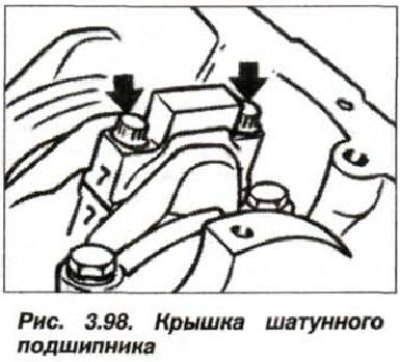
Loosen the bolts (arrows, Fig. 3.98) and remove the connecting rod bearing cap.

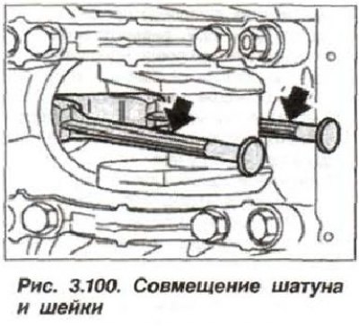
Install the "11.3.460" (or "11.2.470") fixture on the connecting rod bolts (see fig. 3.100) and move the connecting rod with the piston towards the cylinder head, remove this assembly and remove the tools.
Remove the retaining ring (6, see Fig. 3.11) and push out the piston pin.
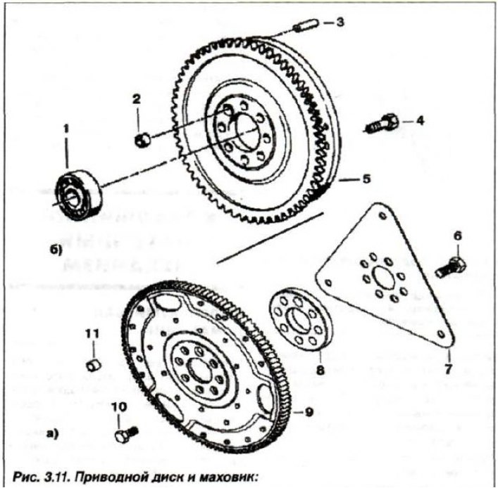
1 - bearing; 2, 11 - centering sleeve (∅ 14.5); 3 - pin; 4 - bolt (M12x1.5x50); 5 - flywheel; 6 - bolt (M12x1.5x28); 7 - slave disk; 8 - spacer washer; 9 - toothed crown; 10 - bolt (M10x17.5)
Check the technical condition of the pistons, pins, connecting rods, bearing shells and piston rings, replace them if necessary. Before installation, measure the nominal clearance between the piston and the bore in the cylinder block, for which:
- measure the piston diameter with a micrometer at a distance "A" of 8.0 mm, from the lower edge of the skirt in a plane at an angle of 90° to the axis of the piston pin (5) and with an offset of 90° in the horizontal plane;
- measure the diameter of the cylinder mirror in three planes with a micrometer (top, middle and bottom) and calculate the average value;
- subtract the piston diameter from the average cylinder diameter;
- the obtained value of the nominal gap should be within the range of 0.01-0.04 mm, the maximum permissible value, as a criterion for the necessary repair when the wear of parts is 0.15 mm.
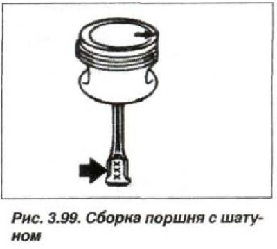
The piston pin should be pushed through the bushing of the upper connecting rod head by pressing the finger and should not have a visible gap or jam. Assemble the connecting rod with the piston so that the connecting rod marking is visible in the selection in pairs, and the arrow on the piston points to the right (Fig. 3.99), to the timing belt cover.
Install the piston pin retaining ring so that its lock is located opposite the recess in the piston.
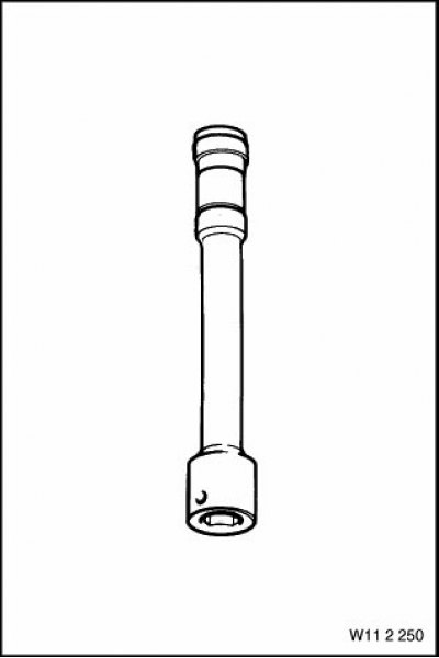
Install the "11.2.470" tools onto the connecting rod bolts.
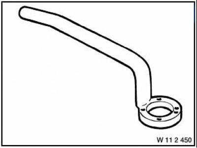
Device 11.2.470
Lightly lubricate the pistons and piston rings with engine oil. Adjust the piston rings so that their ring ends are approximately 120° apart, but they should not be located above the piston bosses.
Compress the piston rings using the tool "11.2.260" (tie-down strap), which should fit tightly around the entire perimeter of the piston surface.
Device 11.2.260
Install the pistons so that the "arrow" on the piston head (bottom) points towards the timing drive. Press the piston into the cylinder block with your fingers, do not apply significant force, due to the risk of breaking the piston rings.
Align the crankshaft journal and connecting rod head (fig. 3.100) and remove the device "11.2.470" (arrows).

Replace the connecting rod bearing shells and lubricate them with engine oil. Install the bearing cap so that the marks ("7", see Fig. 3.98) match on one side of their pairing number.
Insert new, clean connecting rod bolts, lightly lubricated with engine oil.
Using the devices "00.9.120" or "11.2.110" (torque wrench with protractor), tighten both bolts in three parallel steps on each bolt:
- first, tighten to 5.0 N·m (0.5 kgf·m);
- second, tighten to 20 Nm (2.0 kgf·m);
- third, turn it to an angle of 70°.
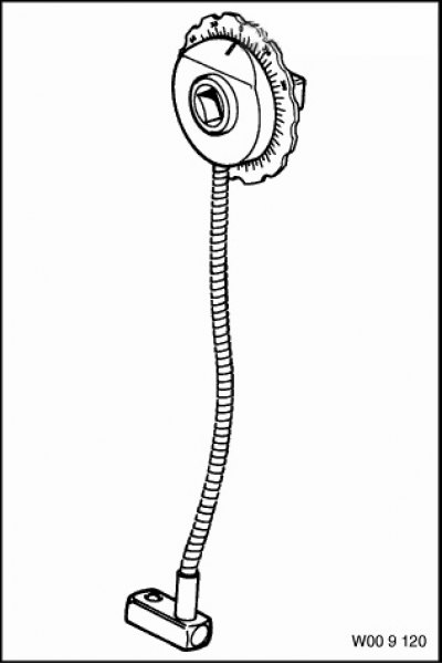
Device 00.9.120
Continue assembling the engine in reverse order, replacing the piston cooling nozzle mounting bolts. Coat the threaded portion of the bolts with a locking agent.