
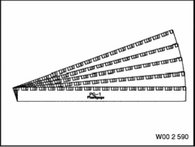
Device 00.2.590

Device 00.9.120
Remove and disassemble the engine. Perform work according to the subsection "Replacing the crankshaft". Pay attention to the repair marking of the crankshaft (12, see Fig. 3.10).
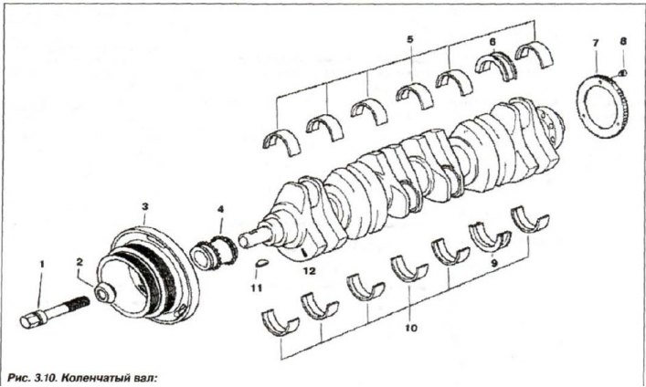
1 - bolt; 2 - spacer washer; 3 - damper; 4 - star; 5, 10 - bearing shell; 6, 9 - thrust bearing shell; 7 - toothed wheel; 8 - lock bolt; 11 - key; 12 - shaft mark
In the lower part of the engine cylinder block, between the main bearing beds, the injectors are installed on two bolts (8, see Fig. 3.3) for cooling pistons.
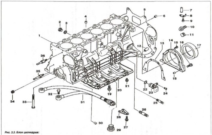
1 - cylinder block; 2 - threaded plug (M14x1.5); 3 - sealing ring; 4 - centering sleeve (∅ 13.5); 5 - shield; 6, 30 - centering sleeve (∅ 10.5); 7, 8 - nozzle; 9 - bolt (M6x16); 10 - plug; 11 - lid; 12 - centering sleeve (∅ 14.5); 13 - seal; 14 - oil seal cover; 15,16 - bolt (M8x32); 17 - oil seal; 18 - centering sleeve (∅ 10.5); 19 - bolt (M8x22); 20 - oil level regulator; 21 - bolt (M6x12); 22 - O-ring (17x3); 23 - crankshaft sensor; 24 - bolt (M6x16); 25 - stud (M8x35); 26 - stud (M10x40); 27 - bolt (M8x22); 28 - intermediate insert; 29 - threaded plug (M24x1.5); 30 - centering sleeve (∅ 13.5); 31 - knock sensor; 32 - bolt (M8x30); 33 - bolt (M10x92); 34 - threaded plug (M14x1.5); 35, 36 - cover pin
Remove the old main bearing shells from the cylinder block housing. Install the shells into the cylinder block (5, see Fig. 3.10)main bearings with a yellow mark and grooves for supplying oil and one retaining lug. Insert the liners into the main bearing caps (10, see Fig. 3.10) without a groove for oil supply and two retaining protrusions.
The centering (thrust) bearing of the crankshaft is installed on support No.6. Insert (6, see Fig. 3.10)with a thrust flange (protrusion) and a hole, install it into the cylinder block.
Note: The color marking of the liners in the main bearing caps must match the marking of the crankshaft.
Place the crankshaft in the bed of the cylinder block housing. The bearing shells are marked yellow, green and white (arrow, Fig. 3.89).
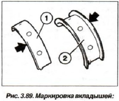
1 - simple insert; 2 - centering insert
When installing the liner, pay attention to the repair size of the main bearing journal.
Bearing caps 1-5 are marked on the outlet side (arrow, Fig. 3.90).
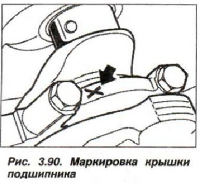
Bearing caps 6 and 7 are not marked. Bearing cap 6 is a thrust bearing.
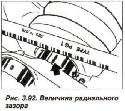
Check the radial clearance of the main bearings. To do this, lay down a clean, dry crankshaft and secure it. The markings on the crankshaft and main bearing shells must match. Install the "00.2.590" device (Plastigage Tour PG1) - plastic calibration wire (dark arrow, see Fig. 3.92).
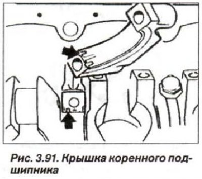
Install the main bearing caps so that the bearing shell guide splines are on the same side (arrows, Fig. 3.91).

Align the bearing caps with the bed along the side plane. Blow out the blind holes with compressed air; moisture and contamination are not allowed. Tighten all the main bearing cap mounting bolts in two steps:
- first, with a torque of 20 N·m (2.0 kgf·m);
- second, turn it to an angle of 70°.
When tightening the covers during the gap check, use the previously removed bolts. Determine the bolt rotation angle using the "00.9.120" device.
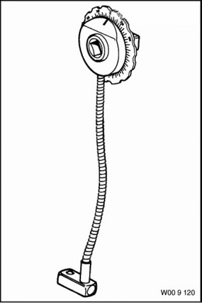
Device 00.9.120
Remove the main bearing caps and measure the radial clearance in the main bearings directly on the shaft journals (arrow, Fig. 3.92), by the width of the flattened calibrated wire.

In this case, use the measuring scale of the calibration wire package. The value of the radial clearance of the crankshaft bearings should be within 0.020-0.058 mm.
If necessary, to adjust the bearing clearance, use new liners with a different color marking. Using alcohol, remove the calibration wire from the crankshaft journal.
Lubricate the crankshaft journals and main bearing shells with engine oil. Install the main bearing caps so that the bearing guide splines are on the same side (see fig. 3.91).
Align the bearing caps with the bed along the side surface. Blow out the blind holes with compressed air, moisture and contamination are not allowed. Install intermediate inserts and tighten the bolts (27, see Fig.3.3) their fastenings.
Lubricate the new main bearing cap bolts with engine oil; do not wash off the factory coating on the bolts. Install and tighten the main bearing cap bolts by hand. Tighten the sheet steel intermediate insert bolts. Install the new (lubricated) main bearing cap bolts and tighten them to a torque of 20 N·m (2.0 kgf·m). Loosen the fasteners of the thrust main bearing cap No.6. Tap the end of the crankshaft at the back and front with a mallet or plastic hammer to center the thrust bearing. Tighten the thrust main bearing cap bolts (No. 6) to a torque of 20 N·m (2.0 kgf·m). Tighten all the main bearing cap bolts by an angle of 70° using the "00.9.120" tool.
Check the crankshaft axial clearance (see fig. 3.87), which should be within the range of 0.080-0.163 mm.
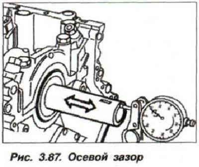
If the permissible axial clearance is exceeded, check and, if necessary, replace the thrust bearing shell, crankshaft and engine block.