
Attention! There is very little space to remove the engine oil pan, so it is necessary to lower the front axle beam. It is not necessary to measure the front wheel alignment angles after completing the work.
Removing the pallet (29, see Fig. 3.14) the oil pan and replacement of its seal (37) must be carried out with an assistant in the following order.
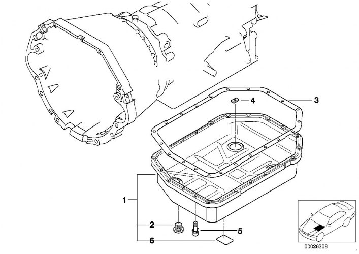
Oil pan
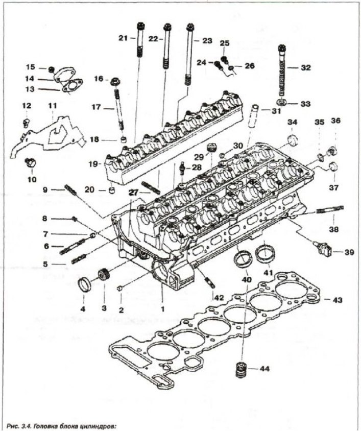
1 - cylinder head; 2.7 - centering sleeve; 3.8 - threaded plug (M8x1); 4 - cover (∅ 28); 5 - stud (M6x30); 6 - stud (M6x60); 9 - stud (M6x28); 10 - bolt (M8x28); 11 - harness holder; 12 - spacer; 13 - seal; 14.30 - lid; 15 - self-locking nut.; 16 - nut (M7); 17 - stud (M7x95); 18, 20 - center, bushing (∅ 9.5); 19 - support bar; 21 - bolt T (M6x50); 22 - bolt T (M6x70); 23 - bolt 7 (M6x100); 24 - threaded plug with sealing ring (M12x1.5x26); 25 - bolt; 26.35 - sealing ring; 27 - stud (M7x39); 28 - hairpin (M7/6x29.5); 29 - threaded plug (M18x1.5); 31 - guide bushing; 32 - head bolt (M10x110); 33 - spacer washer; 34 - cover (∅ 22); 36 - threaded plug (M10x1.0); 37 - cover (∅ 18); 38 - stud (M7x55); 39 - sensor; 40 - exhaust valve seat; 41 - valve seat; 42 - stud (M6x25); 43 - sealing gasket; 44 - check valve
Prepare the equipment "00.0.200", "00.0.201". "00.0.202", "00.0.204", "00.0.208", "00.2.030", "11.0.020", "31.2.220" and "51.2.170".
Remove the engine compartment heater partition. Fix the hood in the installation position using the "51.2.170" device.
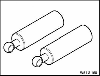
Device "51.2.170"
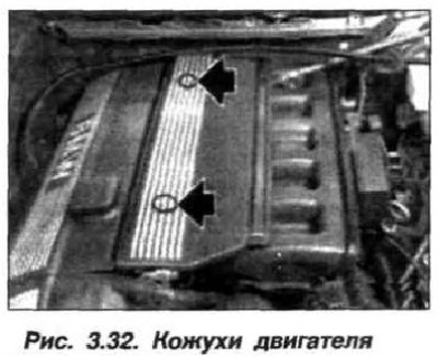
Remove the injector housing (see fig.3.32) and the upper part of the air filter housing together with the air flow meter (AFM).
Secure the engine using the assembly of devices (Fig. 3.74). The supports of the device "00.0.208" must rest on the bolts in both wings of the body.

Remove the alternator drive belt from the power steering pump pulley. Remove the pump and secure it to the body with a wire clip, do not disconnect the hoses.
Unscrew the oil drain plug, drain the oil from the engine and send it for disposal. Disconnect the return hose from the oil separator of the engine crankcase ventilation system. Remove the guide tube of the oil dipstick.
Disconnect the oil lines from the automatic transmission and oil pan. Remove the air filter housing, front auxiliary engine protection panel and stiffening plate.
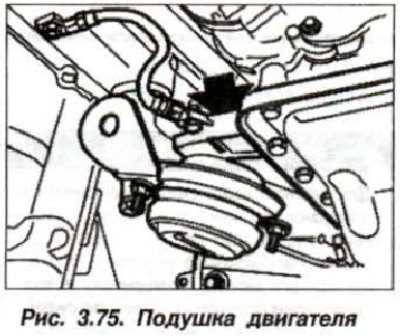
Loosen the upper nuts of the left and right engine mounts (arrow, Fig. 3.75) and lift it using the "00.0.200" tool by approximately 5 mm.
Support the front axle beam with devices "00.2.030" and "31.2.220", using a wooden block.
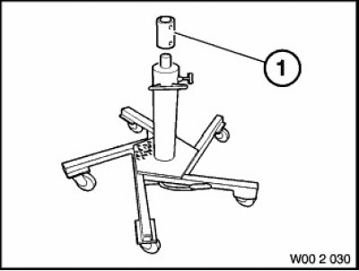
Device 00.2.030
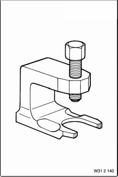
Device 31.2.220
Disconnect the suspension arm brackets from the left and right side members.
Disconnect the left and right stabilizer bar retaining brackets.
Note: The steering gear remains attached to the front axle beam. When lowering the front axle beam, make sure that the steering gear hoses are not stretched.
Loosen the front axle beam mounting bolts, disconnect it from the front side member and carefully lower it by 90-100 mm. Remove the front axle gearbox.
Mark the bolts (M6) (fig. 3.75a) fastenings of the oil pan, since they have different lengths on the timing belt and gearbox sides.
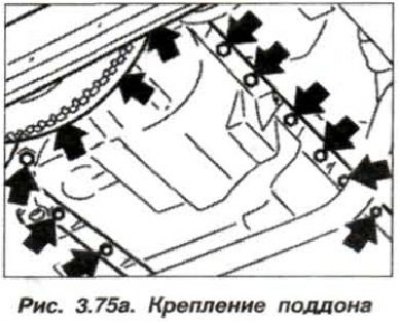
Loosen the oil pan mounting bolts. Remove the oil pan by moving it downwards and backwards.
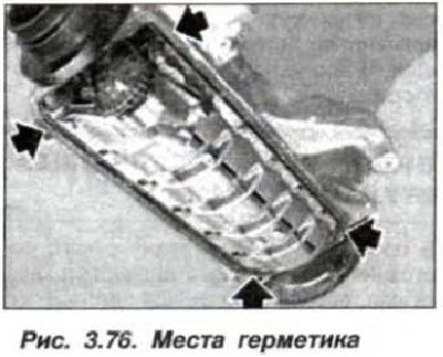
The installation of the oil pan should be carried out in the reverse order, while it is necessary. Using a scraper made of hardwood, clean the sealing surfaces from the remains of the old gasket. In the area of the joints of the rear crankshaft oil seal and the timing cover, apply a layer of sealant type "Drei Bond 1209" approximately 3 mm wide and 2 mm high (Fig. 3.76).
Secure the new sealing gasket to the oil pan using a small amount of thick grease. Check that the gasket is positioned correctly. Insert all oil pan mounting bolts and screw them in by hand, without tightening. Screw in the bolts on the gearbox side, but do not tighten them.
Tighten the bolts on the timing belt and engine block side. Tighten the bolts on the gearbox side. Tighten the mounting bolts to a torque of 10-12 N·m (1.0-1.2 kgf·m), but do not overtighten, otherwise the gasket will lose its tightness.
Install the stiffening plate by tightening the mounting bolts to a torque of 56 N·m (5.6 kgf·m) and then turning them through an angle of 90°. Tighten the engine mount nuts to a torque of 45 N·m (4.5 kgf·m).
Replace the oil drain plug seal and tighten it to 25 N·m (2.5 kgf·m). Fill the engine with oil, replace the ring (26, see Fig. 3.14) steep section on the guide tube (24) and check the oil level in the engine and the power steering drive reservoir (see section "Maintenance").
Take a test drive and check the oil pan for leaks. If necessary, slightly tighten the engine crankcase mounting bolts.