
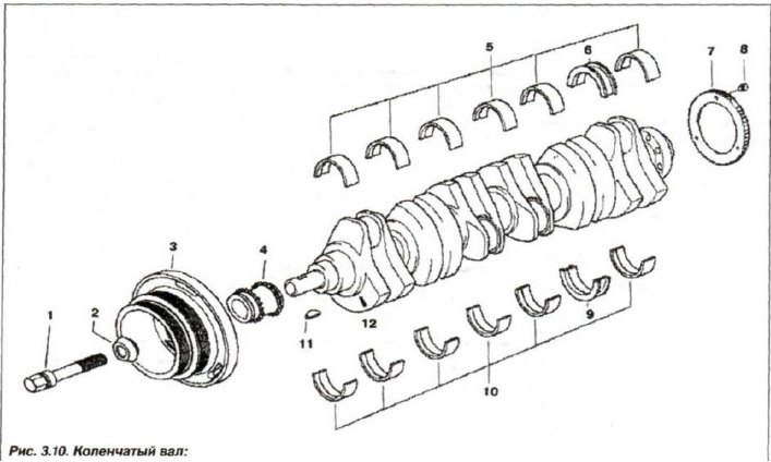
1 - bolt; 2 - spacer washer; 3 - damper; 4 - star; 5, 10 - bearing shell; 6, 9 - thrust bearing shell; 7 - toothed wheel; 8 - lock bolt; 11 - key; 12 - shaft mark
Remove the engine and cylinder head, oil pump, oil level indicator and damper, lower timing belt cover.
Remove the flywheel and all pistons, remove the rear crankshaft oil seal cover. Check the crankshaft axial clearance (Fig. 3.87).
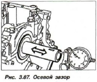
If the permissible axial clearance (0.080–0.163 mm) is exceeded, replace the crankshaft thrust bearing liners.
Remove the bolts securing the intermediate inserts (28, see Fig. 3.3) from sheet metal to increase rigidity and remove them.
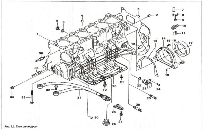
1 - cylinder block; 2 - threaded plug (M14x1.5); 3 - sealing ring; 4 - centering sleeve (∅ 13.5); S - shield; 6, 30 - centering sleeve (∅ 10.5); 7, 8 - nozzle; 9 - bolt (M6x16); 10 - plug; 11 - lid; 12 - centering sleeve (∅ 14.5); 13 - seal; 14 - oil seal cover; 15,16 - bolt (M8x32); 17 - oil seal; 18 - centering sleeve (∅ 10.5); 19 - bolt (M8x22); 20 - oil level regulator; 21 - bolt (M6x12); 22 - O-ring (17x3); 23 - crankshaft sensor; 24 - bolt (M6x16); 25 - stud (M8x35); 26 - stud (M10x40); 27 - bolt (M8x22); 28 - intermediate insert; 29 - threaded plug (M24x1.5); 30 - centering sleeve (∅ 13.5); 31 - knock sensor; 32 - bolt (M8x30); 33 - bolt (M10x92); 34 - threaded plug (M14x1.5); 35, 36 - cover pin
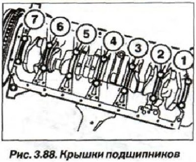
Sequentially loosen all bolts and unscrew the bolts securing the main bearing caps (14 pcs., Fig. 3.88).
Check the marking (digitization) and remove the caps of the main bearings 1-7. If necessary, remove the gear wheel of the engine management system (engine shaft speed sensor). Remove the crankshaft and pay attention to its markings (12, see Fig.3.10).
Replace the crankshaft main and connecting rod bearing shells. Replace the front bearing of the gearbox input shaft. if this is provided for by the design. When installing the gear wheel (7, see Fig. 3.10) KSUD replace the bolts (8, M5 (10.9)) of its fastening and tighten them in two steps:
- first, with a torque of 5.0 N·m (0.5 kgf·m);
- second, turn it at an angle of 45°.