
Attention! After replacing the flywheel, the position of the engine speed sensor must be re-adjusted.
Removing the flywheel must be carried out in the following order. Prepare fixture «11.2.170» and remove the gearbox.
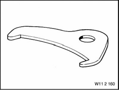
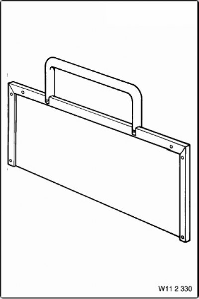
Device 11.2.170
Lock flywheel (drive disk) adaptation «11.2.170» (1, fig. 3.94).
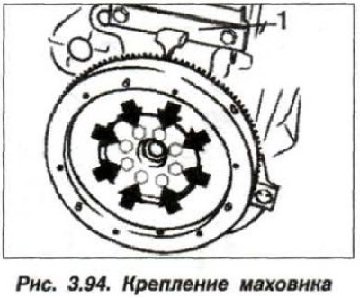
Loosen the mounting bolts and remove the flywheel (or drive disk) RKPP (or automatic transmission).
Inspect flywheel (drive disk) and ring gear for damage, chipping of tooth elements and signs of wear. If found, replace drive flywheel (drive disk) assembled. Separately, the flywheel ring gear must be replaced only at the workshop, where grinding of the flywheel surface is also allowed.
Drive disk installation (flywheel) must be carried out in the reverse order, while checking the centering sleeve for damage and correct installation. Centering sleeve position (1, fig. 3.95) The dual mass flywheel is marked with two grooves (arrows) near the corresponding screw connection hole.
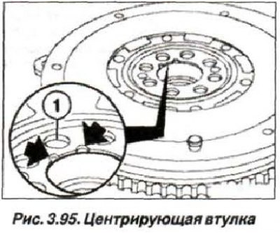
The replacement of the bushing is provided only for a branded part.
Clean the threaded holes for the flywheel mounting bolts on the crankshaft flange. Holes in the flywheel (drive disk) must match. Coat the threaded portion of the new flywheel mounting bolts (drive disk) blocking composition and wrap crosswise, three steps, up to a moment of 120 Nm (12.0 kgf·m).
Replacing the front radial bearing (1, see fig. 3.10) input shaft manual transmission must be carried out using tools «11.2.340», for removal and «11.2.350» in combination with «00.5.500» - for installation up to the stop.
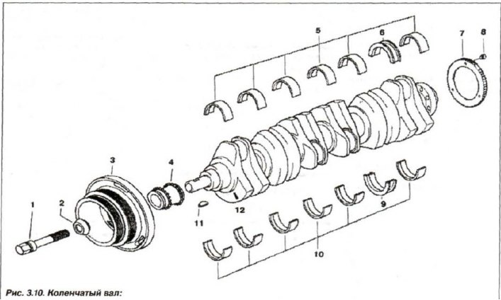
1 - bolt; 2 - gasket washer; 3 - damper; 4 - asterisk; 5, 10 - bearing shell; 6, 9 - thrust bearing shell; 7 - gear wheel; 8 - locking bolt; 11 - key; 12 - shaft mark
Device 11.2.340
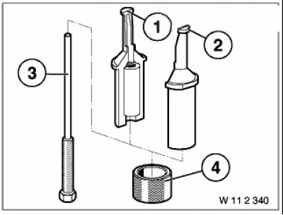
Attachment 11.2.350
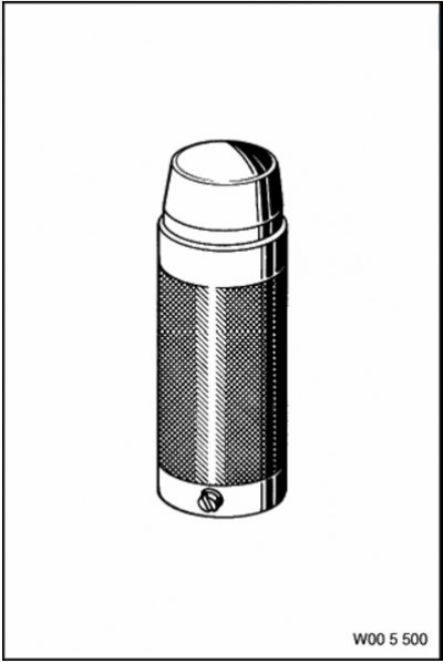
Attachment 00.5.500
Attention! In the version with a needle bearing, the front bearing of the manual transmission input shaft is not installed in the dual-mass flywheel.