
Attention! It is strictly forbidden to replace camshafts without using special tools, due to their possible breakage.
The camshafts can be replaced without removing the engine from the vehicle. The sequence of removing the camshafts is not important. The replacement of the camshafts should be preceded by measuring the axial and radial clearances, which should not exceed 0.15-0.33 mm and 0.02-0.054 mm, respectively.
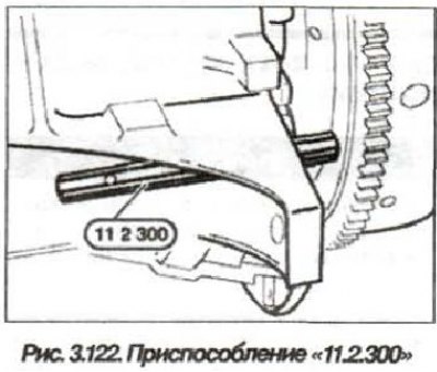
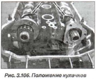
The camshaft replacement must be carried out in the following order. Prepare the tools "00.9.250", "11.2.300", "11.3.240", "11.3.244", "11.3.250", "11.3.260", "11.3.292", "11.4.220", "11.6.150" and "11.6.180". Remove the cylinder head cover. Remove the spark plugs. Set the crankshaft to the TDC position of the compression stroke of the first cylinder (see fig. 3.106)...

... and lock the flywheel using the "11.2.300" tool (see fig. 3.122).

Remove the D-VANOS system actuator.
Unscrew the nut (7, see Fig. 3.12) and remove the timing chain tensioner piston cylinder.
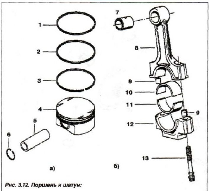
1, 2 - compression ring; 3 - oil scraper ring; 4 - piston; 5 - piston pin; in - retaining ring (∅ 22x1.5); 7 - Upper head bushing; 8 - connecting rod; 9 - centering sleeve; 10 - insert (blue); 11 - insert (red); 12 - connecting rod cover; 13 - connecting rod bolt (47 mm)
Take into account that the piston cylinder is under significant spring pressure. Press the upper tensioner (14, see Fig. 3.13) secondary circuit down and lock it using the device "11.3.292" (rod).
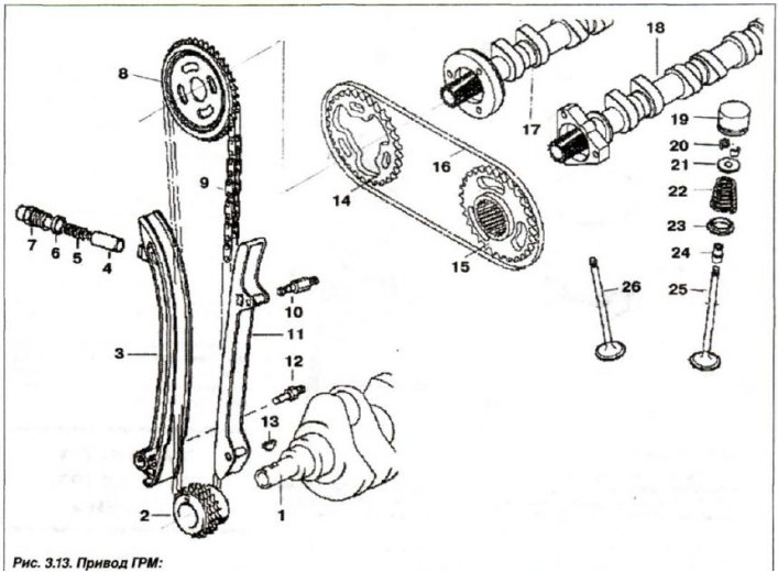
1 - crankshaft; 2,8,14,15 - asterisk; 3 - tensioner bar; 4 - piston; 5 - spring; 6 - sealing ring; 7 - cover bolt; 9.16 - chain; 10,12 - bar bolt; 13 - key; 17 - exhaust camshaft; 18 - intake camshaft; 19 - hydraulic pusher; 20 - valve crackers; 21 - top plate; 22 - spring; 23 - bottom plate; 24 - oil seal; 25 - inlet valve; 26 - exhaust valve
Loosen the nuts (1) and remove the camshaft position sensor wheel (2). Remove the disc spring (3). Loosen the nuts (16) on the intake shaft side and remove the washer (17).
Loosen the bolts (8) on the exhaust shaft side and remove the sprockets (7 and 20) of the intake and exhaust camshaft chain drive together with the drive chain (24), thrust plate (4) and splined shaft (18).
Note: The spline shafts (5 and 18) for the exhaust and intake sides are the same. Install previously used spline shafts strictly in their proper places.
Remove the spline shaft (5) with the toothed sleeve (11). Unscrew the bolts (9,10,15) and remove the tensioner (14) of the secondary chain. Unscrew the studs (12) and disconnect the sprocket (13) from the timing chain by pulling it upwards.
Move forward, remove the sprocket (13) of the timing drive. The drive target remains above the exhaust camshaft. Unscrew the studs (21) on the side of the intake shaft and remove the thrust disk (22). Remove the wheel (23) of the sensor and the intake camshaft position sensor itself.
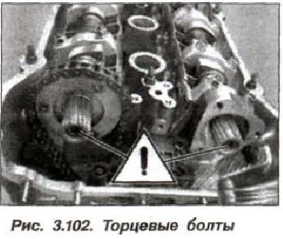
Attention! Bolts (fig. 3.102) do not turn out the ends of the camshafts.
If the camshafts are removed from the cylinder head installed on the engine, then all pistons must be set to the middle position. This will eliminate contact between the valves and pistons, since no piston will occupy the TDC position.
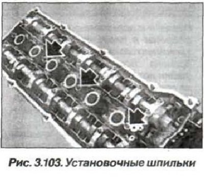
Remove the mounting studs (arrows, Fig. 3.103).
Pull back the device "11.2.300" (see fig. 3.122) back enough to unlock the flywheel.
Raise the timing chain up and, holding it in a taut position, secure it with a wire clip to prevent it from slipping. Turn the crankshaft by the central bolt by 30-40° against the direction of shaft rotation, from the point where the piston of the first cylinder is at TDC at the end of the compression stroke.
Attention! The bearing cap of the intake camshaft of the first cylinder is centered using insert bushings. To avoid skewing of the intake camshaft in the support bar, unscrew the nuts and remove the cover of the first bearing.
Install the "11.3.260" tool on the cylinder head and secure it with bolts (arrows, Fig. 3.104) installed in the spark plug holes of the 1st and 4th cylinders, the tightening torque of the bolts is 25 N·m (2.5 kgf·m).
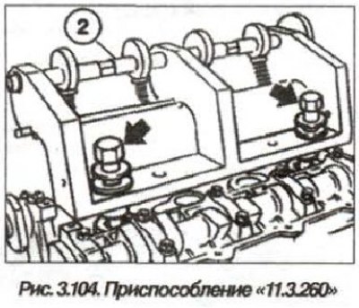
Secure the camshaft bearing caps by turning the eccentric shaft (2) of the "11.3.260" tool clockwise. Loosen all the camshaft bearing cap fastening bolts. Remove the clamping force from the bearing caps by turning the eccentric shaft (2) of the "11.3.260" tool and remove the tool from the cylinder head.
Remove all bearing caps, first make sure they are marked. When reassembling, they must be installed in their original places. The bearing caps of the exhaust camshafts are marked with "A1" through "A7", and the inlet camshafts with "E1" through "E7".
Before removing the cylinder head and valves, it is necessary to first remove the bar assembly with the camshaft bearing caps and hydraulic tappets. To prevent the hydraulic tappets from falling out, install the "11.3.250" devices on top of the tappets. The hydraulic tappets must be installed strictly in their places, so when removing, mark them with a marker.
Remove the support bar assembly together with the cylindrical hydraulic tappets. Check the installation locations of the cylindrical tappets for wear. The support bars are marked "A" (fig. 3.105) for exhaust valves and the marking "E" for intake valves.
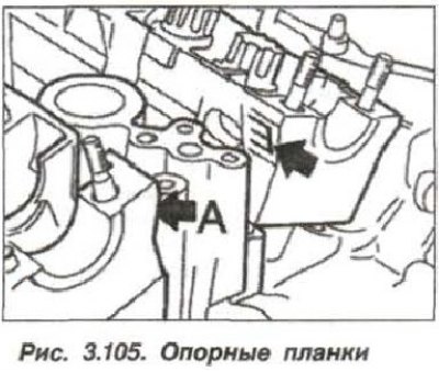
When installing support strips (19, see Fig. 3.4) follow the centering bushings on the bearing mounting studs 2 and 7.
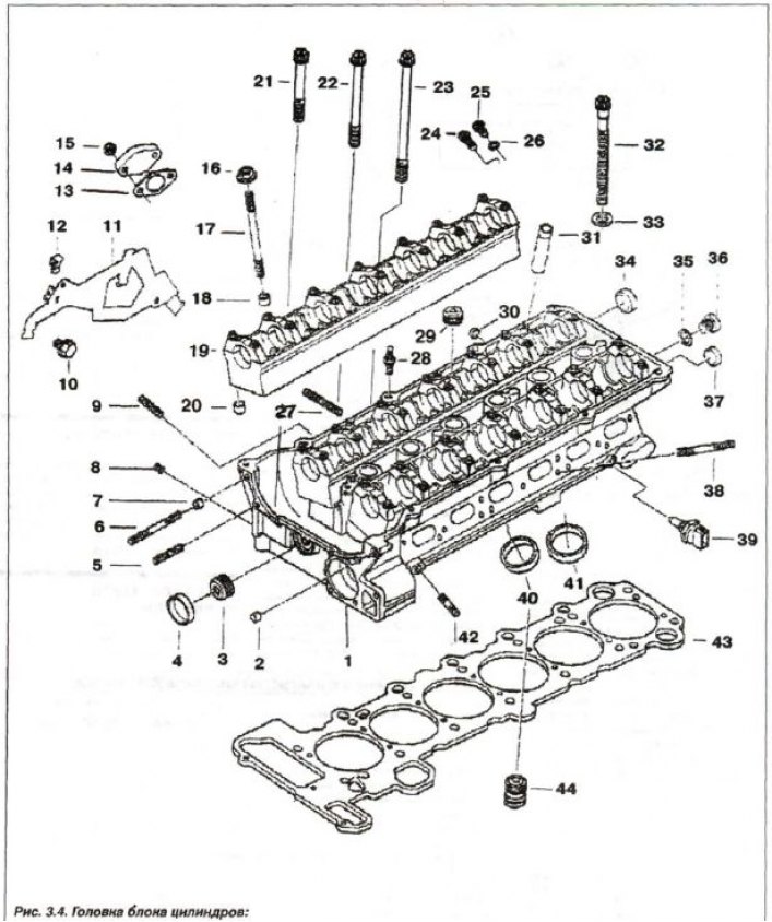
1 - cylinder head; 2.7 - centering sleeve; 3.8 - threaded plug (M8x1); 4 - cover (∅ 28); 5 - stud (M6x30); 6 - stud (M6x60); 9 - stud (M6x28); 10 - bolt (M8x28); 11 - harness holder; 12 - spacer; 13 - seal; 14.30 - lid; 15 - self-locking nut.; 16 - nut (M7); 17 - stud (M7x95); 18, 20 - center, bushing (∅ 9.5); 19 - support bar; 21 - bolt T (M6x50); 22 - bolt T (M6x70); 23 - bolt 7 (M6x100); 24 - threaded plug with sealing ring (M12x1.5x26); 25 - bolt; 26.35 - sealing ring; 27 - stud (M7x39); 28 - hairpin (M7/6x29.5); 29 - threaded plug (M18x1.5); 31 - guide bushing; 32 - head bolt (M10x110); 33 - spacer washer; 34 - cover (∅ 22); 36 - threaded plug (M10x1.0); 37 - cover (∅ 18); 38 - stud (M7x55); 39 - sensor; 40 - exhaust valve seat; 41 - valve seat; 42 - stud (M6x25); 43 - sealing gasket; 44 - check valve
Caution! Lubricate camshafts, bearings and bearing caps, thrust discs, splined shaft toothed rims and toothed bushings with engine oil before installation.
After installing the camshafts and before turning the crankshaft against the direction of its rotation, to set the pistons to TDC, it is necessary to maintain a time interval from 5 min (at T = 20°C) to 30 min (at T = 10°C).
The installation of the camshaft should be carried out in the following order. Pull the timing chain up and install the exhaust camshaft. Place the drive chain on the exhaust camshaft, maintain the above time intervals.
Install bearing caps according to their markings (fig. 3.107), to their former bridges.
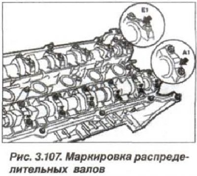
The bearing caps have marks on the outlet side:
- A1 A7 - for exhaust camshaft;
- E1 E7 - for intake camshaft.
Install the shafts so that the tops of the cams on the intake and exhaust shafts (fig. 3.106) the first cylinders pointed at each other (dotted line), symmetrically at its angles.

Install the device "11.3.260" (see fig. 3.104) on the cylinder head as described above.

Turn the eccentric shaft and press the camshaft bearing caps. Tighten the cap mounting bolts (M7) to 14 N·m (1.4 kgf·m) and remove the "11.3.260" tool.
Adjust the camshafts using a modified wrench, the lips are cut off (fig. 3.108).
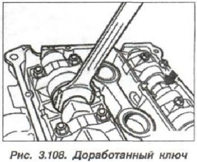
Place the key on the Allen key (arrow).
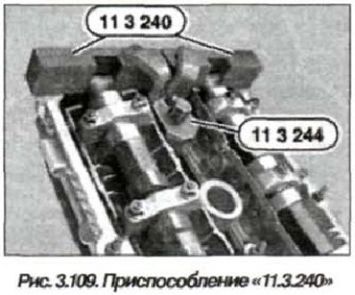
Install the device "11.3.240" (fig. 3.109) on the camshafts in the area of the sixth cylinder.

Adjust the position of the camshafts so that the device fits tightly to the cylinder head, without any gap. Install the device "11.3.244" on the device "11.3.240" and secure it with a bolt screwed into the spark plug hole.
Pull the timing chain up and hold it taut. Return the piston of the first cylinder to the TDC position at the end of the compression stroke by rotating the crankshaft clockwise. Lock the crankshaft in the TDC position at the end of the compression stroke using the "11.2.300" tool.

Attention! Before starting the engine, check that the "11.2.300" device has been removed.
Install the wheel (23, see Fig. 3.13) intake camshaft position sensor.
Place the thrust disc (22) on the intake camshaft and tighten the stud bolts (21, 3 pcs.) to a torque of 20 N·m (2.0 kgf·m).
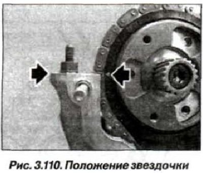
Install the timing chain on the sprocket (13) so that the mark (light triangle) on the star (arrows, Fig. 3.110) was facing the upper plane of the engine cylinder head.
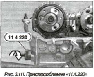
Install the device "11.4.220" (fig. 3.111) into the hole in the cylinder head and screw the adjusting bolt until it touches the chain, without tightening the drive chain itself.
Check the position of the mark (light triangle, see Fig. 3.110) on the sprocket relative to the upper plane of the cylinder head; if necessary, remove and reinstall the sprocket.
Screw the studs into the thrust disc of the exhaust camshaft (12, 3 pcs., see Fig. 3.13) and tighten them to a torque of 20 N·m (2.0 kgf·m). Install the secondary chain tensioner (14) and tighten the bolts (9,10,15) securing it.
Install the toothed sleeve (11) and align it on the camshaft so that the gap between the teeth is located one above the other. Install the splined shaft (5) and align its pin so that it matches the gap between the teeth of the camshaft and the toothed sleeve (11). Install the splined shaft (5) so that the longitudinal holes of the toothed sleeve (11) are symmetrical to the threaded holes.
Place the sprockets with the drive chain into the device "11.6.180" (fig. 3.112), set the gap between the teeth on the intake camshaft chain drive sprocket as shown in the figure fragment.
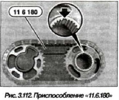
Attention! It is prohibited to change the position of the sprockets relative to the chain when removing them from the device "11.6.180".
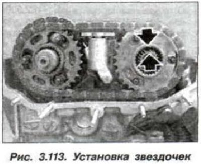
Without changing the position, remove the chain with sprockets from the device "11.6.180" and install them so that the gaps between the teeth on the intake side are opposite each other (arrows, Fig. 3.113).
Adjust the position of the chain with sprockets so that the gaps between the teeth on the intake side are exactly one above the other (arrows, Fig. 3.114).
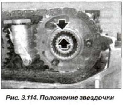
Install the splined shaft (1, Fig. 3.114) so that the spline shaft pin (1) is aligned with the gap between the teeth of the camshaft and the sprocket.
Insert the splined shaft (1) so that approximately 1 mm of the gear ring remains outside. Install the washer (17, see Fig. 3.13) so that the inscription "FRONT" is visible, put the nuts (16, 3 pcs.) and tighten them by hand. Insert the bolts (8, 3 pcs.) on the outlet side, screw them in until they fit tightly, with a torque of about 5.0 N·m (0.5 kgf·m) and loosen by half a turn. Install the thrust disk (4) and the disc spring (3) so that the index "F" is visible.
Note: If the "F" index has worn off during operation, install the disc spring (3) so that its larger diameter faces the drive sprocket, and its smaller diameter faces the camshaft position sensor wheel.
Install the wheel (1, see Fig. 3.116) camshaft position sensor so that the light triangle on the wheel faces the upper plane of the cylinder head.
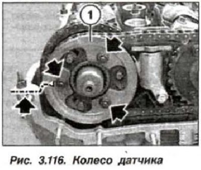
Tighten the nuts (3 pcs., arrows around the circle) and tighten them by hand without tightening them completely. Pull out the splined shaft (5, see Fig. 3.15) forward to the stop.
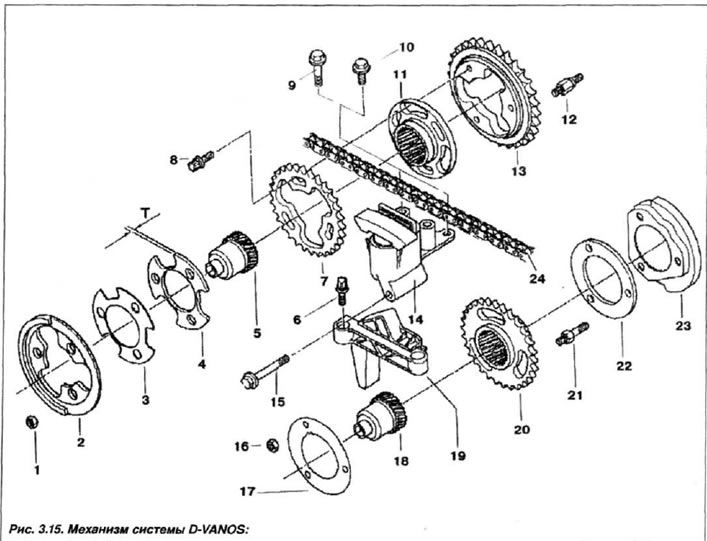
1, 16 - nut (M6); 2.23 - pulse sensor wheel; 3 - disc spring; 4 - thrust disc; 5.18 spline shaft; 6 - bolt T (M6x20); 7,13,20 - asterisk; 8 - bolt T (M7x18); 9 - bolt (M6x40); 10 - bolt (M6x16); 11 - toothed sleeve; 12, 21 - pin; 14 - tensioner; 15 - bolt (M6x55); 17 - washer; 19 - guide; 22 - thrust disc
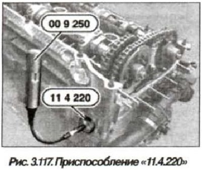
Slightly press the upper tensioner of the secondary chain down and remove the device "11.3.292" (blocker). Using the device "11.4.220" (fig. 3.117), pre-tension the tensioner bar by screwing in the adjusting bolt using the "00.9.250" device or a conventional torque wrench with a torque of 0.7 N·m (0.07 kgf·m).
Press the wheel (2, see Fig. 3.15) exhaust camshaft position sensor, creating a slight tension on the disc spring (3) and tighten the nuts (8. 3 pcs.) only by hand. Check the centering bushings (2.7 cm. Fig. 3.4) for absence of damage and correct installation.
Remove any remaining seals, clean and degrease the sealing surface of the head end.
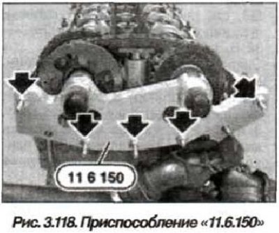
Install the device "11.6.150" (fig. 3.118) just on a clean surface and screw on the nuts (5 pcs., arrows) by hand.
Tighten the mounting nuts of the device evenly so that it fits tightly to the cylinder head over the entire surface.
Screw in the bolts (8, 3 pcs., see Fig. 3.15) on the outlet side and tighten them to a torque of 5.0 N·m (0.5 kgf·m) until they fit snugly.
Tighten the nuts (1, 3 pcs.) on the outlet side and the nuts (16) on the inlet side and tighten them to a torque of 5.0 N·m (0.5 kgf·m) until they fit snugly.
Tighten the bolts (8, 3 pcs., M7) on the exhaust side, initially with a torque of 5.0 N·m (0.05 kgf·m), and then tighten further with a torque of 20 N·m (2.0 kgf·m). Tighten the M6 nuts (1, 3 pcs.) on the exhaust side and the M6 nuts (16, 3 pcs.) on the intake side with a torque of 10.0 N·m (1.0 kgf·m). The stud (21, M7) itself must be tightened with a torque of 20 N·m (2.0 kgf·m).
Caution! Do not allow the engine to turn in the opposite direction.
Pull the tool "11.2.300" back enough to unlock the flywheel. Remove the tools "11.3.244" and "11.3.240" (see fig. 3.109).
Turn the crankshaft two full turns clockwise (720°) and check the position of the camshaft lobes of the first cylinder (see fig. 3.106), which should be facing each other (dotted lines).
Install the device "11.2.300" to lock the flywheel in the TDC position of the first cylinder at the end of the compression stroke. Before starting the engine, remove the device "11.2.300".

Install the "11.3.240" tool on the camshafts (see fig. 3.109).

Despite the correct adjustment of the camshafts, the device "11.3.240" can protrude by up to 1 mm (arrows, Fig. 3.119) relative to the intake side due to manufacturing tolerances of the D-VANOS system components.
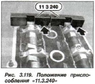
The "11.3.240" device should not protrude relative to the exhaust side, and the valve timing should be readjusted.
Unscrew the fastener and remove the device "11.6.150" (see fig. 3.118).

Install the D-VANOS actuator. Assemble the engine. Reinstall the previously removed components in the engine compartment. Restore the coolant and oil levels. Start the engine and check the tightness of the connections, the oil and coolant levels, and take a test drive.