
Remove the ignition coils and unscrew all the spark plugs. Remove the cylinder head cover, freeing access to the camshafts. Unscrew the nut (7, see Fig. 3.13) and remove the chain tensioner piston cylinder, which is under significant spring pressure.
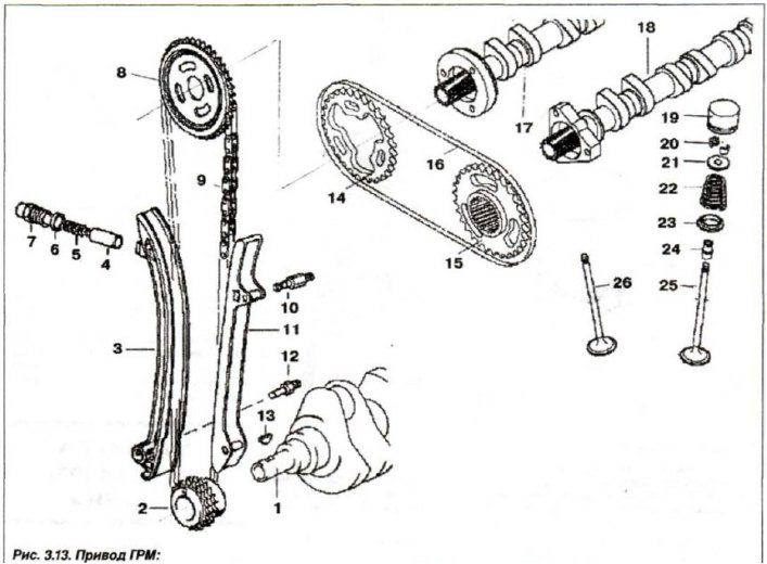
1 - crankshaft; 2,8,14,15 - asterisk; 3 - tensioner bar; 4 - piston; 5 - spring; 6 - sealing ring; 7 - cover bolt; 9.16 - chain; 10,12 - bar bolt; 13 - key; 17 - exhaust camshaft; 18 - intake camshaft; 19 - hydraulic pusher; 20 - valve crackers; 21 - top plate; 22 - spring; 23 - bottom plate; 24 - oil seal; 25 - inlet valve; 26 - exhaust valve
Install the device "11.4.220" (see fig. 3.117) and by turning the adjusting screw only bring it to the tensioner bar.
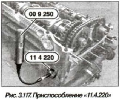
Pre-tension the tensioner bar using the "11.4.220" tool, screwing in its adjusting bolt using the "00.9.250" tool or a conventional torque wrench, applying a torque of 0.7 N·m (0.07 kg·m).
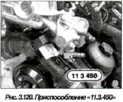
Disconnect the pressure oil line (30, see Fig. 3.63) d-VANOS system and install the device "11.3.450" (fig. 3.120) with a hollow bolt of the pressure oil line.
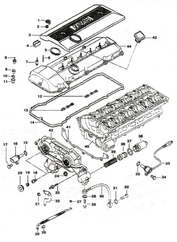
1, 19 - plug; 2 - nut; 3 - protective cover; 4 - overlay; 5, 28, 31, 33, 39 - sealing ring; 6, 23 - mounting pin; 7 - rubber-metal hinge; 8, 9 - cap nut; 10 - spacer washer; 11 - seal; 12, 13, 14 - profile gasket; 15, 37 - sealing ring (17x3); 16, 35 - camshaft sensor; 17, 34 - bolt (M6x16); 18 - precision bolt; 20 - plug with sealing ring; 21 - flange hook; 22 - fastening; 24 - nut M6; 25 - "mass" jumper; 26 - bolt (M6x10); 27 - nut M8; 29, 32 - hollow bolt; 30 - oil pipeline; 36 - EMC; 37 - ring (17x3); 38 - piston; 39 - spring; 40 - cylinder head; 41 - metal seal; 42 - actuator unit; 43 - oil filler cap; 44 - head cover

Attention! Cover the actuator unit of the "D-VANOS" system from above, because when compressed air is supplied, a stream of oil will spray out of the opening of the system.
Connect a compressed air source (2-8 bar) to the device "11.3.450". Turn the engine crankshaft by the central bolt in the direction of rotation until the piston of the first cylinder reaches TDC at the end of the compression stroke (see fig. 3.106), in this case, air pressure must be supplied.
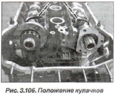
The tops of the camshafts of the first cylinder must be facing each other (dotted lines).
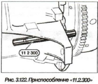
Remove the dust plug (10, see Fig. 3.3) from the hole in the engine crankcase and lock the crankshaft at TDC at the end of the compression stroke of the first cylinder using the "11.2.300" device.
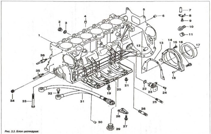
1 - cylinder block; 2 - threaded plug (M14x1.5); 3 - sealing ring; 4 - centering sleeve (∅ 13.5); S - shield; 6, 30 - centering sleeve (∅ 10.5); 7, 8 - nozzle; 9 - bolt (M6x16); 10 - plug; 11 - lid; 12 - centering sleeve (∅ 14.5); 13 - seal; 14 - oil seal cover; 15,16 - bolt (M8x32); 17 - oil seal; 18 - centering sleeve (∅ 10.5); 19 - bolt (M8x22); 20 - oil level regulator; 21 - bolt (M6x12); 22 - O-ring (17x3); 23 - crankshaft sensor; 24 - bolt (M6x16); 25 - stud (M8x35); 26 - stud (M10x40); 27 - bolt (M8x22); 28 - intermediate insert; 29 - threaded plug (M24x1.5); 30 - centering sleeve (∅ 13.5); 31 - knock sensor; 32 - bolt (M8x30); 33 - bolt (M10x92); 34 - threaded plug (M14x1.5); 35, 36 - cover pin

Attention! After finishing the work and when cranking the engine shaft, do not forget to unlock the crankshaft by removing the device "11.2.300".
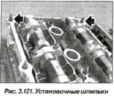
Remove the mounting studs (2 pcs., arrows, Fig. 3.121).
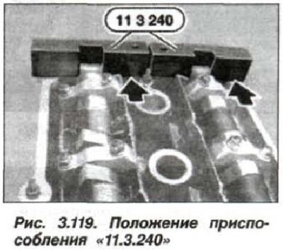
Install the device "11.3.240" (see fig. 3.119) on the camshafts.

Despite the correct adjustment of the camshafts, the "11.3.240" device may protrude by up to 1 mm relative to the intake side due to manufacturing tolerances of the D-VANOS system components and the gap in the gear engagement. The "11.3.240" device must not protrude relative to the exhaust side, in which case the valve timing must be readjusted.
Disconnect the compressed air source and remove the device "11.3.450" (see fig. 3.120).
Connect the pressure oil line with new sealing rings (28, see Fig. 3.63), tightening torque of hollow bolt M14x1.5 (29) — 32 Nm (3.2 kgf·m).
Remove the device "11.3.240" (see fig. 3.119), device "11.2.300" (stopper) and install the dust plug (10, see Fig. 3.3) into the fixing hole.
 |
 |
Loosen the tension of the timing chain bar and remove the device "11.4.220" (see fig. 3.117).

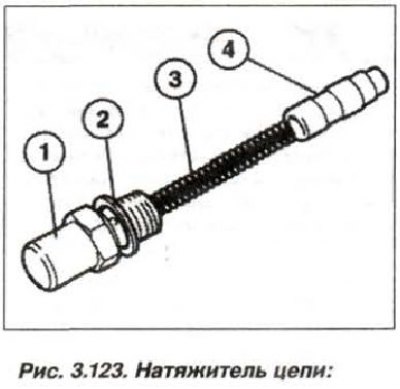
Replace the sealing ring (2, see Fig. 3.123) and install the timing chain tensioner plunger cylinder. Tighten the piston cylinder nut (M26x1.5) to a torque of 70 N·m (7.0 kgf·m).
Assemble the engine and check the crankshaft locking.
(The article text was copied from an online resource: «BMWman.ru»)