
Attention! Work on replacing oil scraper caps must be carried out when the corresponding cylinder is at BDC.
One of the reasons for increased oil consumption is wear of oil scraper elements (oil deflectors) valve stem caps. Replacement can be carried out without removing the cylinder head from the engine using a special device and a source of compressed air with a pressure of 6-8 bar (kgf/cm²).
The valve stem oil seals must be removed in the following order. Remove the camshafts. Remove the cylindrical hydraulic valve lifters. Set the piston of the corresponding cylinder to the TDC position by turning the crankshaft by the central bolt securing the belt pulley to the shaft until the camshaft cams take the positions shown in Fig. 3.106.
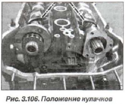
In this case, the piston of the 1st cylinder will occupy the TDC position at the end of the compression stroke.
Apply a chalk line on the crankshaft pulley at the bottom and a second mark on the engine, strictly at an angle of 180° and move the cylinder piston to the BDC position, continuing to turn the crankshaft with a key (by 180°) until the chalk lines coincide. The piston of the 1st cylinder will take the BDC position.
Remove all spark plugs. Install the device in the spark plug hole of the corresponding cylinder. Connect the device with an air hose to the pressure source. Supply air to the cylinder under a pressure of 6-8 bar (kgf/cm). Install the device and use it to remove the spring and valve plates.
Attention! Tightly seated valve crackers may be loosened by lightly tapping the device with a plastic hammer. Install the valve stem seal only if a plastic mandrel (sleeve) is available.
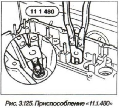
Remove the device, remove the valve stem seals using the device "11.1.480" (see fig. 3.125).
The installation of the valve stem seal should be carried out in the reverse order, while it is necessary to lubricate the valve stem with engine oil.
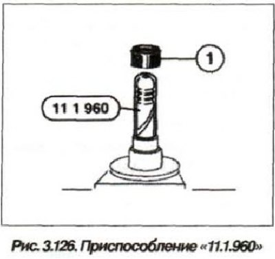
Install the plastic mandrel "11.1.960" onto the valve stem (fig. 3.126), which is included in the delivery set of oil scraper caps (1).
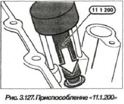
Lightly lubricate the inside of the oil seal with engine oil. Install the oil seal in the "11.1.200" type device (fig. 3.127).
Carefully and smoothly place the oil seal on the valve guide mandrel. Remove the plastic mandrel and the device for installing it. Assemble the valve, installing the plates, spring and valve crackers in place, as described above. Replace the oil seals of the adjacent valves of this cylinder.
Stop the air supply to the cylinder and remove the "653/3" type device from the spark plug threaded hole.
Similarly, replace the oil seals on the valves of the remaining cylinders. Install the cylindrical hydraulic tappets and the valve camshaft. Assemble the engine and check its operation in idle mode.