
Withdrawal
Disconnect the ground wire from the battery.
Attention: When the battery is disconnected, the information in the electronic memory devices, such as the engine trouble memory or the radio security code memory, is erased. Disconnect the battery only when the ignition is switched off, so as not to damage the fuel injection system control unit. When disconnecting the battery, follow the instructions in sections "Radio" And "Removing and installing the battery".
Attention: On vehicles with six-cylinder engines, the battery is located in the luggage compartment next to the spare wheel.
Raise the car.
Remove the exhaust system.
Remove the heat shield from the exhaust system.
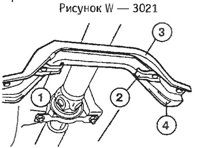
If present, unscrew fasteners -1- and -2-. Unscrew clip -3- from underbody of vehicle, while paying attention to its installation position for subsequent installation. The wide lug -4- faces the front of the vehicle.
Unscrew the cardan shaft from the gearbox with a hinged disk. To avoid overtightening of the pivot plate, only loosen the nuts, not the bolts.
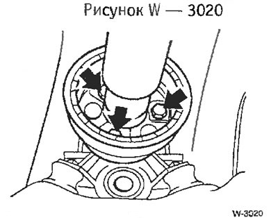
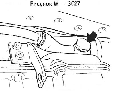
Use a pipe wrench to loosen the threaded ring -arrow- in the middle of the propshaft by a few turns.
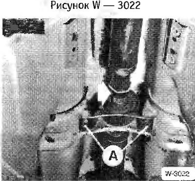
Unbolt center bearing -A- for propshaft.
Tilt the cardan shaft down and pull it out of the centering pin.
Attention: Tie up the cardan shaft, do not allow the hinges to fall.
With the propshaft removed, detach the retaining clip -1- from the selector rod, remove the washers on both sides of the selector rod and pull out the selector rod.
Disconnect the reversing light switch wire from the rear of the transmission.
Remove clutch slave cylinder.
Attention: The hydraulic lines remain connected.
Suspend the engine on a crane or chain hoist, see section "Removing the engine". Tighten the cable so that the engine does not drop after the rear gearbox support is unscrewed.
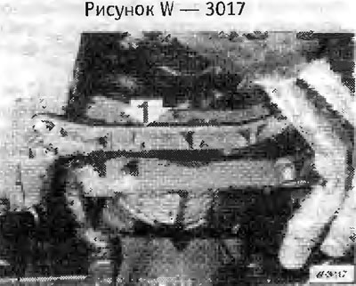
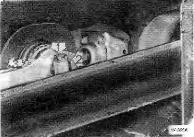
Unbolt cross member -1- from underbody and gearbox.
Lower the engine just enough so that it does not touch the bulkhead in the engine compartment.
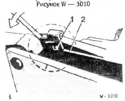
Take the spring -1- out of the lug -2- on the housing with a screwdriver and tilt upwards.
Pull out the support pin.
Automatic transmission
Disconnect the shift cable from the gearbox.
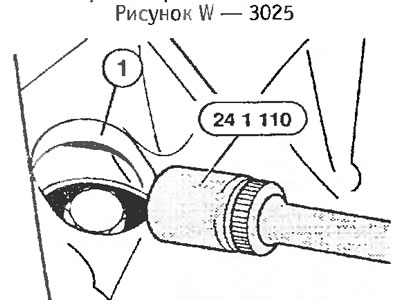
Disconnect the electrical connector from the box by turning the knurled nut on the connector to the left. Disconnect the second, smaller RPM sensor connector by pressing on the wire retainer.
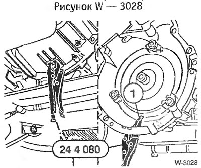
Remove the cover on the side of the opening -1- on the engine crankcase. Sequentially unscrew the 3 bolts securing the torque converter with a narrow head of the wrench, while preventing the bolts from falling into the housing. To bring the bolts to the hole, turn the engine by the hexagon of the crankshaft belt pulley.
Support the box from below with a garage jack. The box should be supported only by the body, and not by the oil sump.
Unscrew the 2 brackets securing the oil lines to the oil cooler on the engine block and engine oil sump.
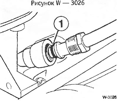
Unscrew the oil line from the oil cooler.
Attention: Oil flows out, substitute a vessel. Dirt must not get into the tubes, so put on plastic bags or rubber rings.
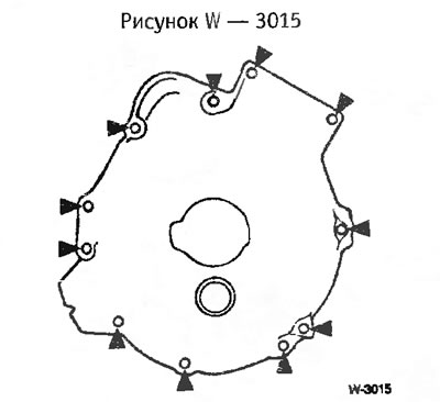
Loosen the gearbox-to-engine bolts. The bolt pattern on the flange is the same as on a manual transmission.
Fix the torque converter so that it cannot move, for which use pliers. Remove box from engine.
Loosen gearbox bolts with socket wrenches.
Separate the gearbox from the engine and pull it down with an assistant.
Installation
Check clutch before installation.
Check the ease of movement of the release bearing. Lubricate the bearing, e.g. Molykote Longtherm 2. If noises were previously observed during the operation of the bearing when depressing the clutch, replace the surviving bearing.
Turn on any transmission.
Raise the box and in a horizontal position enter the clutch. If the input shaft does not fit into the clutch disc, turn the propshaft flange by hand accordingly.
Attention: Make sure that there are two centering bushes between the engine and gearbox.
Tighten the gearbox mounting bolts on the engine with washers.
Tightening torques for bolts with Torx heads: M8 bolts - 25 Nm; bolts M10 - 45 nm; bolts M12 - 70 nm.
Tightening torques for conventional bolts: M8 - 25 Nm; bolts M10 -50 nm; M12 bolts - 80 nm.
Raise the gearbox and secure it to the cross member with a tightening torque of 25 Nm.
Install slave cylinder.
Install the support pin by coating it with Kluber PoLylub GLY 801.
Use a screwdriver to put the spring -1- on the spout -2- (Figure W 3010).
Insert shift rod. Put a washer on the pin and fix the shift rod with a lock washer.
Connect the reversing light switch wire.
Automatic transmission (Drawing W 3025)
Pull the pliers out of the box body and screw in the 3 torque converter bolts through the hole in the box.
Attention: Install only M10 threaded bolts with a thread length of 16 mm. Install spring washers. Tighten the bolts to 45 Nm. Failure to comply with the requirements will result in the destruction of the box.
Remove the plugs and screw the oil pipes with new gaskets to the oil cooler.
Screw the oil pipe fittings to the engine oil sump and engine block.
Connect the electrical wires to the box. Turn the knurled nut to the right.
Install and adjust shift cable.
Pour oil into the box.
Install driveshaft.
Install the rear cross member with the bolts tightened to 20 Nm. If equipped, install the two exhaust system mounts on the cross member.
Install heat shield.
Install the exhaust system.
Check the oil level in the gearbox.
Connect ground wire to battery.