
Removal of the manual transmission is carried out without removing the engine, through the bottom of the car. Removal of the manual transmission is necessary when the clutch is removed or the manual transmission is subject to replacement or repair.
Removal of the manual transmission type "S5D 280Z" must be carried out in the following order. Prepare the tools "00.2.030", "23.0.130", "23.0.131", "23.0.132" and "23.0.133".
Attention!
- When the negative terminal of the battery is disconnected, the data in the ECU-KSUD is erased. Before starting work, read the information from the engine management system memory and record it.
- When removing and installing the manual transmission, it should not rest on the primary shaft, otherwise the driven clutch disc will become deformed.
Disconnect the power supply by removing the key from the ignition switch and disconnect the "-" terminal of the battery. Remove the jumper connecting the "ground" to the body. Remove the intermediate muffler, the right front and rear heat-insulating screens.
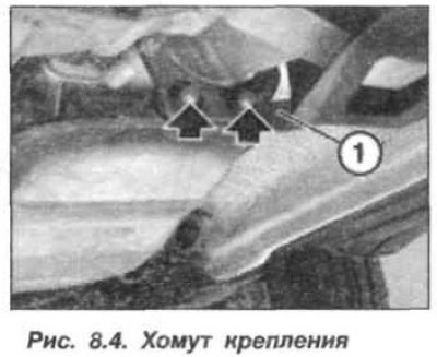
Remove the stiffening plate, front and rear engine sump guard panels and drain the transmission oil. Loosen the anti-roll bar fastening and move it forward. Remove the front propeller shaft, unscrew the bolts and remove the clamp (1, Fig. 8.4) exhaust pipe mounts.
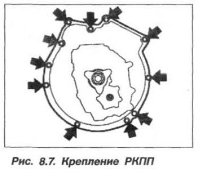
Mark the relative positions of the engine and manual transmission with paint or a marker to facilitate their subsequent assembly. Mark the bolts, as they are of different lengths. Unscrew the three lower Torx-type bolts (M8x50) securing the manual transmission to the engine (see fig. 8.7).
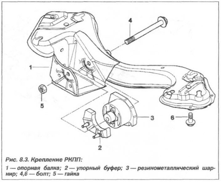
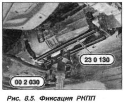
Assemble the "23.0.130" device together with the "00.2.030" and "23.0.130" devices (Fig. 8.5), support the manual transmission and transfer case (TC) with them. Remove the cable harness from the mounting brackets on the manual transmission housing. Unscrew the mounting bolts (6, see Fig. 8.3), disconnect the support beam (1) from the body. When disconnecting the rubber-metal hinge (3), rotate only the nut (5), holding the bolt head (4, M12x1.5x220).
Attention! Do not allow the cardan shaft to fall, due to the possibility of damaging the joints and the rubber boot of the CV joint.
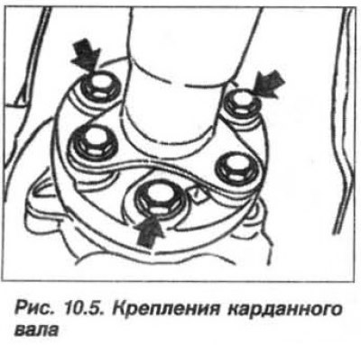
Loosen the bolts (3 pcs., arrows, see Fig. 10.5) fastening the cardan joint, while holding the bolt head and turning the nut. Holding the cardan shaft, unscrew the nuts fastening its intermediate support to the body. Bend the cardan shaft downwards, pressing the intermediate support downwards and disconnect the shaft from the flange of the secondary (output) shaft of the manual transmission, move it to the side and fix it to the body with a wire clamp, preventing it from breaking in the joint in order to avoid damaging the CV joint.
Caution! Make sure that the exhaust manifold does not come into contact with the anti-roll bar.
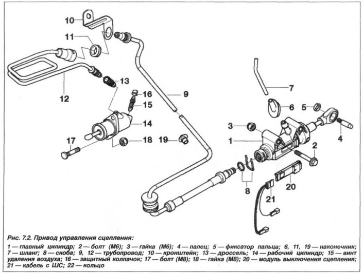
Slightly lower the manual transmission to perform further work. Without touching the clutch pedal any more, unscrew the mounting nuts (18, see Fig. 7.2), remove the clutch slave cylinder and secure it to the body with a wire clip. Leave the hydraulic line connected. Do not touch the clutch pedal again.
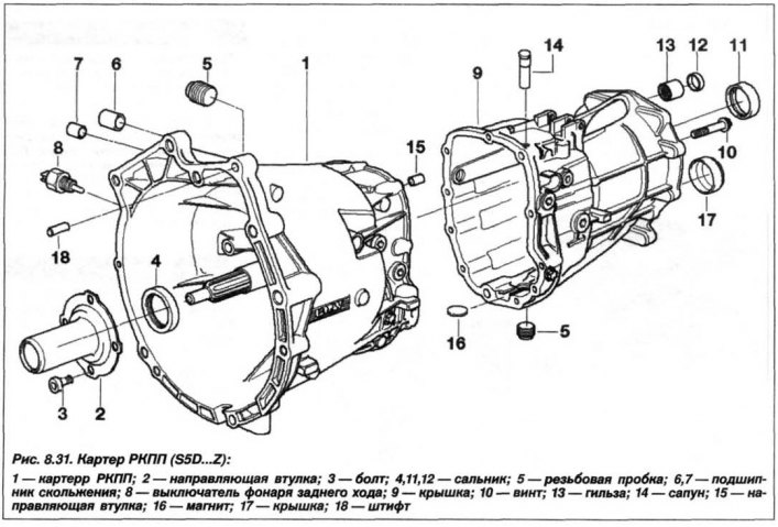
Disconnect the control unit from the switch (8, see Fig. 8.31) reverse light and remove the wiring harness from the holders on the gearbox housing.
Remove the locking clip (11, see Fig. 8.16) gear shift drive rods (10), remove the rod (10) from the housing (12) and remove the mounting washers.
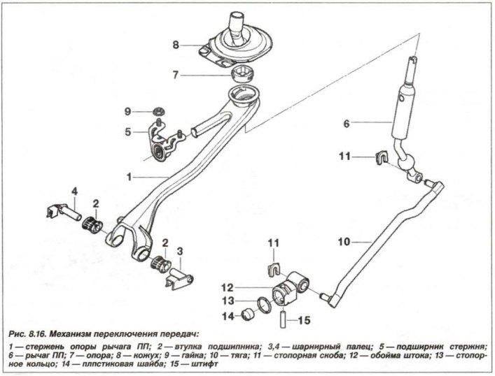
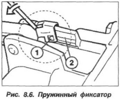
Use a screwdriver to pry up the spring clip (1, Fig. 8.6) and unhook it from the boss (2) on the crankcase. Fold the spring retainer (1) upwards and remove the hinge pins (3 and 4, see Fig. 8.16). Place a garage jack under the engine, in the area of the first cylinder, using a wooden spacer, to prevent it from tipping over when the manual transmission is removed.
Attention! When removing and installing the manual transmission, make sure that the manual transmission does not hang on the primary (input) shaft, otherwise the driven clutch disc may be deformed.
Loosen the remaining bolts in a crisscross pattern (arrows, Fig. 8.7) fastenings of the manual transmission to the engine and unscrew them completely. In this case, the manual transmission rests only on the assembly of devices.
Together, with an assistant, separate the engine and the manual transmission, moving it back, remove the gearbox, turn it as far as possible (approximately 10°) counterclockwise, and remove the manual transmission from under the car.
The installation of the manual transmission should be carried out in the reverse order, while it is necessary to check the technical condition of the clutch and make sure that the release bearing rotates easily and lubricate it with plastic grease of the type "Molykote-Longtherm-2".
Check the driven disk for rust in the splines and replace if necessary. Use a rag to remove old grease and dust from the splines of the driven disk, which is formed when the friction lining wears out.
Attention! The bearing should only be wiped, not washed. The bearing should not make noise when rotating.
Check the installation of the centering bushings (18, see Fig. 8.31) on the manual transmission housing. Check the installation of the clutch basket on the flywheel. Remove the coupling and the clutch release fork, clean them and lubricate them in the appropriate places. Check if the grease on the primary (input) shaft of the manual transmission is sticky. If the grease is sticky, replace the driven clutch disc.
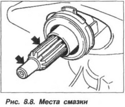
Clean and lubricate the splines and journal of the primary shaft of the manual transmission with a thin layer (Fig. 8.8) of antifriction paste of the type "Microlude GL 261" or apply an anti-friction spray such as "Esso UNIREX 52". The amount of grease is pea-sized so that excess grease cannot get onto the friction surface of the clutch and disrupt its operation.
Engage one of the forward gears in the manual transmission, lift it up and, in the suspended position, engage the clutch.
Attention! If during installation the primary shaft of the gearbox does not enter the splines of the driven clutch disc, then manually turn the secondary shaft by the flange of the cardan shaft installation until the splines match.
Screw in the manual transmission mounting bolts, together with the washers, and pre-tighten them, one after the other, to a torque of 2.0 kgf·m. Further tightening should be done crosswise, with the final torque specified below.
Tightening torques of fastening bolts (nuts), N·m (kgf·m):
- torx type bolt:
- m8 22 (2.2);
- m10 43 (4.3);
- m12 72 (7.2).
- hex head bolt:
- m8 25 (2.5);
- m10 49 (4.9);
- m12 74 (7.4).
- working cylinder fastening nut – 22 (2.2);
- intermediate support fastening nut – 21 (2.1);
- cV joint mounting nut, flat/knurled head:
- M8 32 (3.2) / 43 (4.3);
- M10 64 (6.4) / 70 (7.0).
- transverse mounting bolts to the body – 49 (4.9);
- transverse fastening nuts to the manual transmission – 74 (7.4);
- nuts for fastening clamps (M8) – 15 (1.5);
- flexible coupling of the cardan shaft – 100 (10.0);
- (replace self-locking nuts)
- filler and drain plugs – 50 (5.0).
Tighten the stiffening plate mounting bolts in two stages – 56 Nm (5.6 kgf·m) + 90°.
Reversing light contact switch (M12) – 18 (1.8);
Install the anti-roll bar and secure it with new self-locking nuts, tightening it to a torque of 60 N·m (6.0 kgf·m).
When installing the removed parts, it is prohibited to apply significant force so that the parts are not subjected to excessive mechanical loads. Install the clip (12, see Fig. 8.16) gear shift rod. Lubricate the gear shift rod (10) with plastic grease such as "Kluber Polylub DLY 801" and install the traction (with washers and locking clips, 11) into place. Fill the manual transmission with oil and check its level.
Reinstall all removed components and, if necessary, adjust the gear shift mechanism.
When replacing the S5D 280Z manual transmission from an old one to a new one, the following parts should be transferred to the new manual transmission:
- release bearing and clutch release fork;
- clutch slave cylinder mounting studs;
- reverse light switch;
- gear selector rod sleeve;
- check the damping washer (14, see Fig. 8.16) in the rod holder for damage and, if necessary, replace it;
- breather (14) and safety sleeve from the gear selection rod.
The S5D 39Z gearbox is equipped with the M57 engine and is secured to the body using a beam (1, see Fig. 8.3) and a rubber-metal hinge (3), similar to the S5D 280Z manual transmission. Manual transmissions differ only in their reinforced design, since they bear different loads due to the increased torque of the M57 engine transmitted to the wheels of the car. Removal and installation of the S5D 39Z manual transmission should be carried out in the same order as with the S5D 280Z manual transmission.