
Note: It is recommended to replace the O-rings every time the steering gear is disassembled, even if they appear to be in good condition. Before installing the rings, thoroughly clean the grooves intended for them.
Select the thickness of the adjusting rings 6 installed in the intermediate cover so that the sealing edge of the ring with grooves 3 has a slight pre-tension.
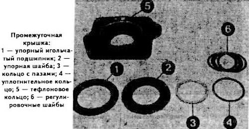
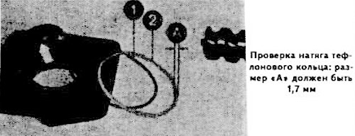
Check the tension of the Teflon ring 5 of the intermediate cover. Install the thrust washer and thrust needle bearing in the intermediate cover. Install the sealing ring 1 and the Teflon ring 2. The dimension "A" (see photo) of the Teflon ring should be 1.7 mm.
Remove and save the gaskets, mounting and adjusting rings, and thrust needle bearing.
Install the worm shaft without the Teflon and sealing rings and the grooved ring on the valve box without the sealing gasket. Install the outer ring of the ball bearing, the thrust needle bearing and the thrust washer.
Secure the valve box with the intermediate cover to the steering gear housing, tightening the mounting bolts crosswise to a torque of 3.1 kgf·m.
Check the friction moment of the worm shaft. If necessary, adjust it by selecting the thickness of the thrust washer.
Loosen the intermediate cover mounting bolts, replace the sealing ring, Teflon ring, thrust needle bearing and insert the worm shaft into the intermediate cover.
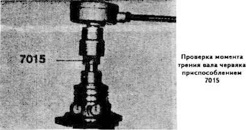
Install the BMW 7015 device and measure the friction torque of the worm shaft in a vertical position (see photo). If it is less than the norm, install a thicker Teflon ring.
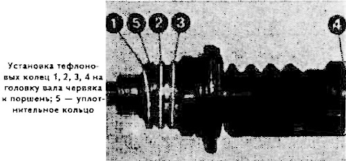
Check the total friction torque of the worm shaft head with new Teflon rings 1-4 installed on the piston head, with the O-ring, groove ring, seal and adjusting rings.
Insert the worm shaft head into the valve box, secure this unit to the steering gear housing and adjust the preload by placing adjusting washers under the grooved ring.
Note: It is prohibited to remove the valve plungers 1 (see photo), since during repair their adjustment and correct installation relative to the hydraulic block is impossible.
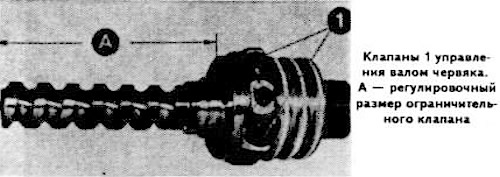
Check the adjustment dimension "A" (see photo) for the steering limiting valve, which should be 107-0.20 mm.
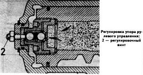
Adjust the position of the stop screw 2 (see picture) so that the limiting valve opens approximately 2 mm before touching the stop.
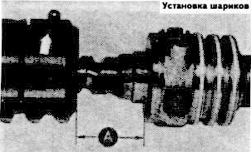
Insert the worm shaft into the piston, maintaining dimension "A" (see photo) equal to 6 mm, and insert 16 balls into the grooves of the shaft through the front hole, while simultaneously inserting the worm into the crankcase.
Insert seven balls into the ball guide tube, securing the last two balls with bearing grease.
Secure the top half of the ball guide tube with the retaining spring.
Use device 7015 to check the friction moment of the worm shaft with the balls installed. In doing so, turn the worm shaft no more than 3.5 turns to prevent the balls from falling out.
Replace the remaining steering gear parts in the reverse order of disassembly and install it in place.
Since the 1978 model year, the installation of the steering gear housing is carried out taking into account the following:
- set the steering wheel and wheels to the straight-ahead position. The marks on the steering gear housing and steering shaft must match;
- make sure that the bolt securing the flexible coupling of the steering shaft is located in the locking groove of the shaft. Secure the bolt with a cotter pin.