
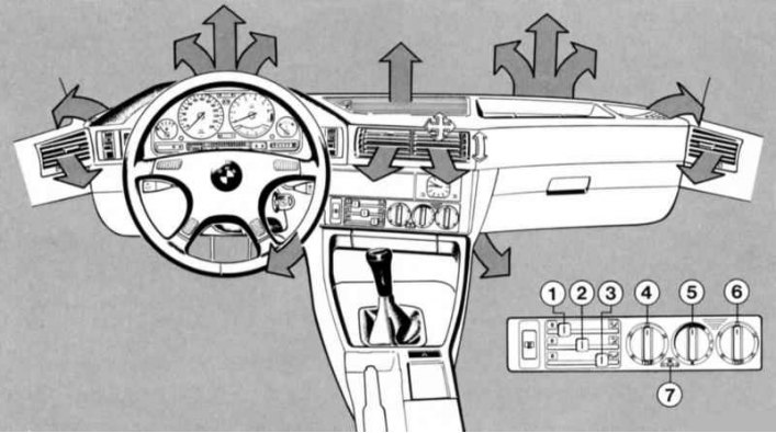
1-3 — Air supply distribution levers
Smooth regulation of heated air distribution.
- Lever to the left - closed;
- Lever to the right - fully open.
1 — Lever for distributing air supplied to the windows
The air coming through the deflectors is directed to the windshield and front side windows.
2 - Lever for distributing air supplied to the middle
The air supply is regulated by turning the deflectors in the middle of the instrument panel, in the front doors, and also on the upper side of the instrument panel.
3 — Lever for distributing air supplied to the feet
Air flows through deflectors located in the front and rear footwells. On vehicles without a microfilter, these nozzles must always be approximately half open for the temperature sensor to function properly (except for the glass defrosting mode), which corresponds to the middle position of the lever.
Rear compartment ventilation
The rear compartment can be ventilated using the deflectors in the center console, regardless of the position of the lever on the instrument panel. Only fresh air enters through them.
4, 6 - Rotary temperature switches for the left and right sides of the passenger compartment
The scales indicate the approximate values of the temperature set in the cabin. The selected temperature is reached extremely quickly and, as a rule, should not change further (automatic temperature control).
To avoid unwanted temperature fluctuations, turn the switches gradually.
If the rotary temperature switch on the driver's side is turned to one of the end positions, the automatic temperature control on both the driver's side and the right side is switched off. (These positions can be used as an emergency switch for heating or cooling in the event of a malfunction of the electronic temperature control system).
5 - Switch and rotary switch for the amount of air supplied
Position 0 - the system is switched off, the air supply is blocked.
Turn clockwise from the fixed position - the system is on, a minimum amount of air is supplied, the fan operates at minimum capacity.
Further rotation to the right - the amount of supplied air increases, minimum fan performance.
Increased fan performance - stages 2-4.
For the electronic temperature control system to function properly, the rotary switch must be set to at least the 12 o'clock position.
For maximum intensive heating of the windshield and side windows, use:
7 — Maximum glass heating control diagram
The maximum effect is achieved if the engine is warmed up.
Fogging of glass occurs due to the formation of condensation due to temperature differences or when the air humidity is too high. Condensation can only be eliminated by blowing a large amount of warm air onto the glass.
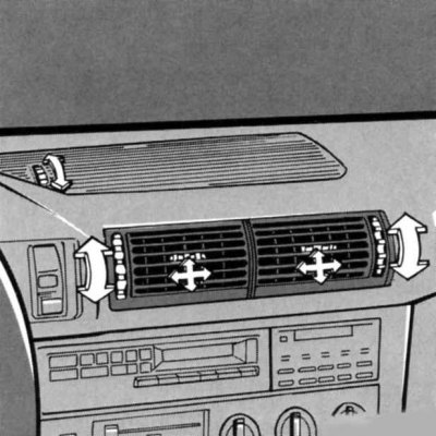
Comfortable driving conditions - thanks to layered distribution of conditioned air: warm feet - cool head
The temperature of the air supplied through the nozzles on the instrument panel and front doors can be changed by rotating roller 1:
- rotate right - warmer;
- left rotation - colder;
The direction of the air flow can be adjusted individually by deflectors, and its quantity - by a roller. The blades of the deflector located on the top of the instrument panel are fixed and ventilation of the middle part of the cabin through it occurs indirectly.