
Table of contents: Switches and controls located on the…↓ Multifunctional steering wheel ↓ Controls located in the doors ↓ Controls located near the instrument…↓ Controls and interior equipment on…↓ Overhead controls and interior…↓ Storage compartments and armrests ↓ First aid kit and warning triangle ↓
- Home
- BMW 7 Series
- E38
- General information
- Manual
- Interior controls and equipment
Interior controls and equipment (BMW 7 Series E38)
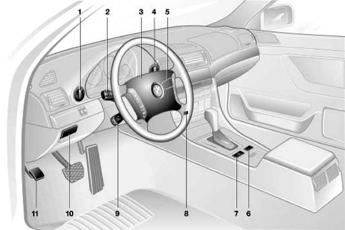
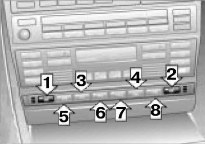
Interior controls and equipment
1 - External lighting switch
2 — Left steering column switch
3 — Horn switch and driver's front airbag unit
4 - Fog light switch
5 — Right steering column switch
6 - Single lock switch
7 — Hazard warning switch
8 — Rear window heating switch
9 — Electric steering column switch
10 — Parking brake release handle
11 — Parking brake pedal
The description of the instrument cluster is given in Section Instrument cluster, – as well as a trip computer with a multi-function display and an HVAC system control unit – they are described in Part Comfort devices. Some controls are considered.
Switches and controls located on the steering column
Left steering column switch
Do not leave exterior lights on when the engine is off to avoid draining the battery.
The left steering column switch (2) is designed to control the direction indicators, switch between low and high beam headlights, high beam headlight signaling, turn on the parking lights, and also to control the trip computer.
The description of the trip computer control is given in Section Comfort devices.
1. To turn on distant headlights (for this the low beam must be on) move the left steering column switch lever away from you. Switching on the high beam headlights is accompanied by switching on the corresponding K/L in the instrument cluster (see section Instrument cluster).
2. To switch back to low beam mode, return the lever to its original position (pull it towards you).
3. For high beam alarms headlights, pull the switch lever towards you. In this position, the high beam will turn on regardless of the position of the key or ignition switch, and will work until the switch is released.
4. To turn on left pointer or right turn with the ignition on, pull the steering column switch lever downwards or upwards accordingly. The corresponding turn signal indicator will flash in the instrument cluster. Once the turn is completed, the switch will automatically return to the neutral position.
5. When changing lanes, you can use lane change indicators, to turn on which you should slightly pull the switch up or down, without bringing it to the stop, and hold it in this position. After releasing, the switch will automatically return to the neutral position.
6. To turn on parking lights on one side of the vehicle when set to position "0" in the ignition switch, pull the steering column switch lever down or up accordingly.
7. It is possible to use the low beam headlights for some time after leaving the parked car. To do this, briefly pull the switch lever towards you after turning off the engine.
Right steering column switch
To avoid damaging the windshield wiper mechanism, do not turn them on if the glass being cleaned is dry, and do not move them by hand. In frosty weather, before turning on the windshield wipers for the first time during a trip, check that the blades are not frozen. To avoid damaging the windshield wiper blades, do not allow them to come into contact with gasoline or other solvents. To avoid damaging the windshield washer pump, do not use it if the washer fluid reservoir is empty, or continuously for more than 30 seconds.
The windshield wiper arms are partially located under the hood. To bring them into a vertical position (for example, to replace brushes), turn off the ignition with the windshield wipers running at the right moment.
Do not leave the rain sensor on while washing your car.
The right steering column switch is used to control the windshield wipers and windshield washers. The windshield wipers and windshield washers only operate when the ignition is on.
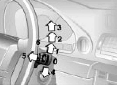
Positions of the right steering column switch
0 - Neutral position
1 - Interval mode or rain sensor activation
2 - Normal speed
3 - High speed
4 - Single cycle
5 - Windshield washing
6 - Rotary control for intervals or sensitivity of the rain sensor
On models without a rain sensor, with windshield wipers on at normal/high speed when the vehicle is stationary they operate respectively in interval mode/at normal speed.
If the vehicle is equipped with headlight washers, they are automatically turned on every fifth time the windshield washer is turned on.
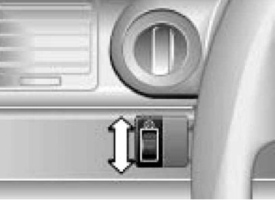
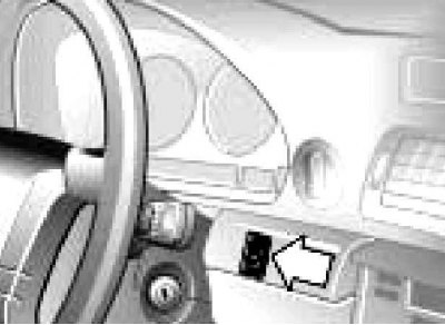
Electric steering column switch
It is possible to store up to three positions of the seat, outside rear-view mirrors and steering column – see Section Adjusting seats and headrests.
The steering column should be adjusted so that the steering wheel is in line with the driver's chest. A position in which the steering wheel is in line with the driver's face is incorrect because it reduces the protective function of the driver's front airbag.
Do not adjust the steering column while driving, as this may cause loss of control of the vehicle.
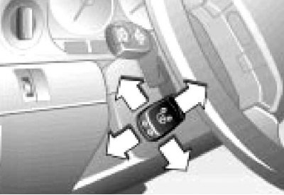
To change the height and angle of the steering column, press the switch in the corresponding direction.
To make it easier to get in and out of the car, the steering wheel position automatically changes accordingly. This function works based on the position of the key in the ignition switch and the position of the driver's door.
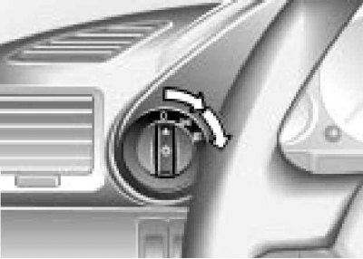
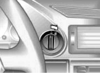
Ignition and steering wheel lock switch
Ignition switch (lock) is located on the right side of the steering column and has the following 4 positions:
0 — This position is used to lock the steering wheel and remove the key from the ignition switch. To lock the steering wheel, remove the key from the ignition switch and turn the steering wheel slightly. On models with AT, the lock cannot be moved to this position unless the "P" mode is selected; in addition, in the "0" position, or when the key is removed from the ignition switch, the AT mode selector lever is locked in the "P" position. The lever can be moved out of this position by turning the key to the position "2".
1 — In this position, the steering wheel is unlocked, the ignition is off, and the power supply to the vehicle's auxiliary electrical consumers is on.
2 — In this position, the ignition and all electrical consumers of the car are on. This is also the normal position after starting the engine. Before starting the engine, when turning the key to this position, you should check for a short-term operation of the indicator lamps built into the instrument cluster (see section Instrument cluster).
Do not leave the ignition key in position "2" with the engine off, as this will quickly discharge the battery.
3 — Used to start the engine. When the ignition key is held in this position, the starter will turn the engine over. While the starter is running, some electrical components are disconnected, making it easier to start the engine. When released, the key returns to the position "3".
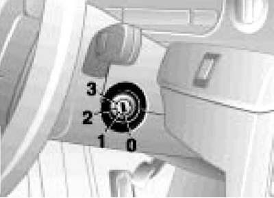
Ignition switch positions.
Multifunctional steering wheel
The description of the control of the temperature control, telephone and audio system is given in Part Comfort devices.
It is possible to install one of two types of multifunctional steering wheel.
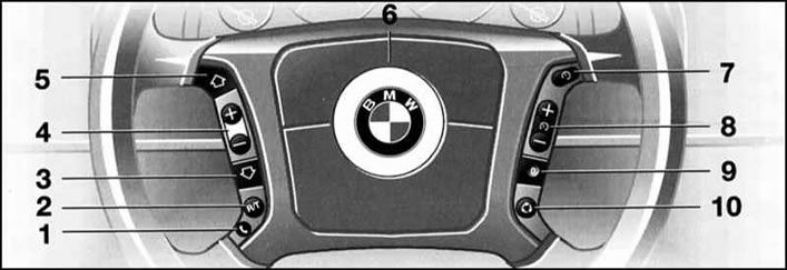
Multifunction steering wheel, type 1
1 - Accept an incoming call, start dialing and end the call (with short press), or turn voice control on and off (while holding the switch)
2 - Radio and telephone: selection
3-5 - Radio and phone: search for a station in reverse/forward order or move through the phone book; rewind/fast forward in CD and cassette player mode
4 - Radio/phone: volume control
6 - Horn switch
7-9 — Tempostat control buttons (see section Tempostat)
10 — Air circulation mode or steering wheel heating
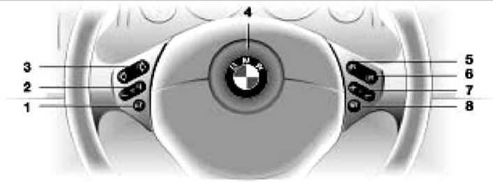
Multifunction steering wheel, type 2
1 - Accept an incoming call, start dialing and end the call (with short press), or turn voice control on and off (while holding the switch)
2 - Radio/phone: volume control
3 - Radio and phone: search for a station in reverse/forward order or move through the phone book; rewind/fast forward in CD and cassette player mode
4 - Horn switch
5-7 — Tempostat control buttons (see section Tempostat)
8 - Radio and telephone: selection
The steering wheel heating only works when the ignition is on. When the heating is turned on, the indicator built into the switch turns on.
The horn switch is built into the steering wheel trim, press it without much force, as the horn switch is integrated with the driver's front airbag unit.
Controls located in the doors
It is possible to store up to three positions of the seat, outside rear-view mirrors and steering column – see Section Adjusting seats and headrests.
1. The doors contain switches for controlling the power windows (see section Windows doors) and outside rear-view mirrors.
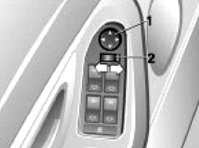
1 - Adjusting the position
2 - Selecting a mirror for adjustment
2. The position of the outside rear-view mirrors can be adjusted either using the switch or manually by pressing on the corresponding edge of the mirror.
3. To adjust one of the mirrors, move the switch (2) to the appropriate position, and then use the switch (1) to adjust the position of the mirror.
4. Mirror heating is switched on automatically when the ignition is turned on.
5. If the switch (2) is in the driver's side mirror adjustment position, when reverse gear is engaged, the front passenger side mirror will automatically tilt down, providing a better view when parking.
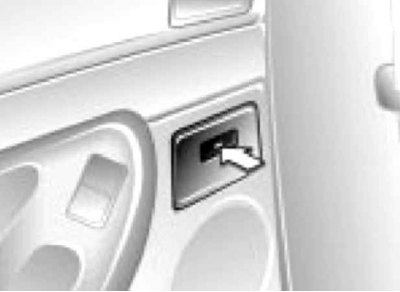
Ashtrays are located in the front part of the rear doors.
6. To open the ashtray, press the recess on its lid.
7. To clean the ashtray, pull it out.
Controls located near the instrument cluster
Outdoor Light Switch is designed to turn on the side lights (position
In position "0" the exterior lighting is off. If the ignition switch is in the position "0", then when the driver's door is opened with the exterior lighting on, a corresponding message is displayed on the text display in the instrument cluster. When the low beam headlights are turned on, the interior door handles are illuminated. When the vehicle is equipped with the DRL system (daytime running lights) the headlights turn on automatically when the ignition is turned on.
Instrument illumination intensity regulator is located under the external lighting switch and is designed to set the brightness of the instrument lighting to suit the driver.
Fog light switch located to the right of the instrument cluster.
When the fog lights are switched on, the corresponding K/L in the instrument cluster is switched on. The high beam headlights are switched off.
RDC system switch (tire inflation pressure control), if equipped, it is located under the fog light switch.
The RDC system is designed to warn the driver of low tyre inflation pressure by means of messages displayed on the text display in the instrument cluster.
1. To activate the system, turn on the ignition and hold the switch down until the message appears "SET TIRE PRESSURE" ("Setting the tire inflation pressure").
2. After a few minutes of driving, the RDC system will determine the reference value of tire inflation pressure. If the pressure drops, a message will be displayed "CHECK TIRE PRESSURE" ("Check the tire inflation pressure").
3. When a tire is punctured, a message is displayed "TIRE DEFECT" ("Tire malfunction"), accompanied by an audible signal-replace the wheel.
The spare wheel is equipped with the electronics necessary for the RDC system to operate, so the system will continue to operate after the wheel has been replaced. If the RDC system malfunctions, a message is displayed "TIRE CONTROL INACTIVE" ("Tire inflation pressure monitoring is not active").
Controls and interior equipment on the center console
A description of the ventilation, heating and air conditioning systems, the audio and navigation systems, as well as the trip computer with a multi-function display is given in Part Comfort devices; the transmission controls are described in Section Using an automatic transmission (AT).
Description single lock switch (6 in the illustration Interior controls and equipment) is given in Section Access, protection.
Hazard warning switch (7 in the illustration Interior controls and equipment) works in any position of the ignition switch. To turn on the hazard warning lights, press the switch button; to turn it off, press the button again. When the hazard warning lights are on, their indicators in the instrument cluster flash synchronously with all the direction indicators. The hazard warning light switch is illuminated when the outside lighting is on.
On models with heated front seats the corresponding switches are located in the center console.
1, 2 — Heated front seats
3 — ASC T/DSC systems
4 - Sunshade
5, 8 - Free seats
6 — PDC System
7 — EDC System
By successively pressing one of the switches, you can select one of three heating modes for the corresponding seat. The minimum heating mode is accompanied by one indicator turning on, and the maximum heating mode is accompanied by three indicators turning on. In each mode, the temperature is regulated by a thermostat. The maximum heating mode can be turned on by holding the switch down for a while. The switches have built-in heating indicator lights.
Parking assistance switch (PDC, if equipped accordingly) is designed to forcibly turn it on and off. The PDC system is automatically turned on one second after the reverse gear is engaged with the ignition on and turns off when the reverse gear is disengaged or when driving with a trailer. The forcibly turned on system turns off automatically if the car has traveled a distance of about 50 m or its speed has exceeded 30 km / h. The system operates using four ultrasonic sensors built into each bumper to determine the distance to the nearest object. The sensors in the front bumper, as well as the side sensors in the rear bumper, work at a distance of up to 60 cm, and the two central sensors in the rear bumper - at a distance of up to 1.5 m. A change in the distance to the object is represented for the driver by a change in the pauses between the sound signals of the PDC system - the closer the obstacle, the shorter the pause. When less than 30 cm remains to the obstacle, the sound becomes continuous. The sound signal turns off after about 3 seconds if the distance to the obstacle does not change during this time (for example, when moving along a wall). A fault in the PDC system is indicated by a continuous high-pitched signal and a flashing indicator.
PDC systems should not be relied upon completely, as objects that fall into the blind spot of the sensors are not detected by the system and do not trigger an alarm. Object recognition may also exceed the limits of what is physically possible with ultrasonic measurements, for example with the drawbar and trailer coupling, as well as thin objects and painted surfaces. To ensure that the PDC sensors are fully functional, they must be kept clean.
Automatic stability control system with traction control/dynamic stability control switch (ASC T/DSC) is designed to force it to be switched on and off. The listed systems increase the vehicle's stability during acceleration and turns and are switched on automatically when the engine is started. As confirmation of the proper functioning of the system, when the ignition is switched on, the corresponding K/L briefly lights up in the instrument cluster (see section Instrument cluster). If the ASC T/DSC system K/L does not turn off after starting the engine or lights up while driving, the system is faulty or has been forcibly turned off. Flashing K/L indicates that the system is active. To turn off the system (e.g. to "rock" the car, start driving in deep snow or on a slippery road), press the "ASC" or "DSC" switch (depending on the configuration) – K/L lights up. When pressed again, the system switches off and K/L goes out. More detailed information about the ASC T/DSC system is provided in Section Auxiliary systems.
Electronic Suspension Stiffness Control Switch (EDC, if equipped accordingly) is used to switch between its automatic and sports programs. The EDC system constantly provides the necessary shock absorption of the chassis, contributing to greater vehicle comfort and driving safety. After each engine start, the system is activated in automatic mode and operates in all vehicle speed ranges and under any vehicle load. To activate the sports program with the ignition on, press the "EDC" switch. The K/L next to the letter "S" will light up. To switch back to automatic adjustment, press the switch again, the K/L will go out. More detailed information about the EDC system is provided in Section Auxiliary systems.

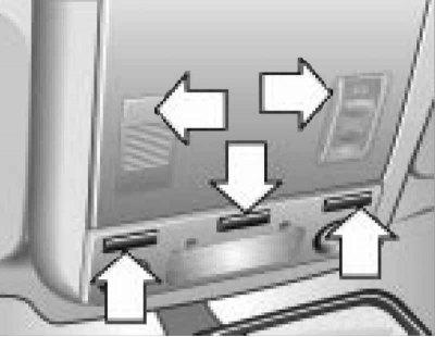
Cup holder is located at the bottom of the center console.
1. To bring the cup holder into working position, press on the recess in its lid.
2. To remove the cup holder, press it into the center console.
Do not use the cup holder while the vehicle is moving, as objects placed in it may cause injury to the driver and passengers in the event of an accident, sudden braking or acceleration. Moreover, do not place unsealed containers with hot liquids in the cup holder while the vehicle is moving, as the driver may get burned and lose control of the vehicle if the liquid splashes.
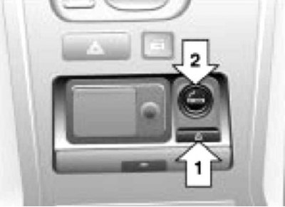
Ashtray and cigarette lighter are located in the center console between the seats, under a common cover.
1. To open the lid, press the recess in it. To empty the ashtray, press the button (1) and pull out the ashtray.
2. The cigarette lighter (2) is installed in the power take-off socket and operates regardless of the position of the ignition key. To use the cigarette lighter, press it and release it. After the cigarette lighter has heated up to the required temperature, it will automatically return to its original position.
Do not keep the cigarette lighter pressed after it is ready for use, as this may cause it to overheat; for the same reason, the cigarette lighter should be removed from its socket if it does not automatically return to its original position for a long time. The ashtray should not be used to store any items, since a fire may occur if lit cigarettes or matches come into contact with them.
The cigarette lighter and cup holder for rear passengers are located at the rear of the center console.
Instead of a cigarette lighter, auxiliary electrical devices can be connected to the power take-off socket (for example, a vacuum cleaner or a portable lamp) power up to 200 W at 12 V.
Overhead controls and interior equipment
The sunroof control switch is described in Section Upper hatch.
Interior lighting turns on and off automatically.
Switches on the overhead console
1 - Outdoor lighting switch
2, 3 - Reading lamps
4 — Speaker grille (when equipped with a telephone)
5 — Upper hatch cover control
1. If you need to turn the interior lighting on or off manually, press the switch (1).
2. To prevent the interior lighting from turning on under any circumstances, hold this button for 3 seconds.
3. To return to normal operation of the interior lighting, press the button briefly.
When the side lamps are turned on, the indicators built into the left and right edges of the switch are turned on.
Reading lamps can be switched on and off separately using the switch (2 and 3) located next to the corresponding lamp.
Universal Transceiver (with appropriate equipment) designed for use instead of several (up to three) separate transceivers (for example, from a garage door or security system). The universal transceiver unit is located in the ceiling console.
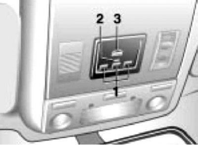
Universal Transceiver
1 - Channel call buttons 1 to 3
2 — Indicator
3 - Receiver for programming
To program the universal transceiver, follow these steps:
- Turn on the ignition;
- Press and hold the channel 1 and 3 call buttons simultaneously until the indicator starts flashing (this clears the memory of all channels);
- Bring the separate transceiver to the universal transceiver receiver at a distance of no more than 5 cm;
- Press the transmit button on the separate transceiver and the channel call button on the universal transceiver simultaneously. Release the buttons when the indicator starts flashing at an increased rate.
Interior rear view mirror with two sensors (back and front), providing automatic dimming of the mirror depending on the lighting conditions. However, when reverse gear is engaged, the dimming is automatically switched off.
Sun visors can be folded forward and to the side. On the inside of the sun visors, behind the sliding cover, there are built-in cosmetic mirrors. If the ignition switch is in the position "1" or "2" and the cosmetic mirror is open, its backlight turns on.
Storage compartments and armrests
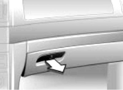
Main storage compartment located in the instrument panel opposite the front passenger seat.
The box has a lock that can be opened and locked only with the master key (see section Access, protection). When the glove box is opened, its backlight is switched on. The open lid of the glove box can be rotated, providing more convenient access from the driver's side. A rechargeable flashlight is fixed inside the glove box, on the left.
Do not store the flashlight in the glove box when it is turned on, as this will cause it to overcharge and fail.
1. To fold down the rear armrest, pull the corresponding loop.
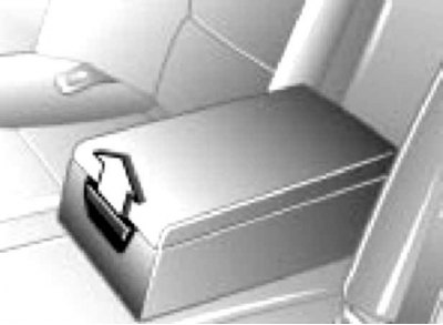
2. There is a storage compartment inside the armrest, which can be accessed by pulling the button.
Some models are equipped with a multifunctional rear armrest, under the cover of which is a control unit for some of the car's devices.
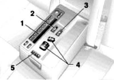
Multifunctional rear seat armrest
1 - Multifunctional display for controlling the audio system and trip computer (with limited functions)
2 - Activation of the rear window sunblind
3 — Front passenger side shoulder support
4 — Electric drive of the front passenger seat
5 — Front passenger seat position memory
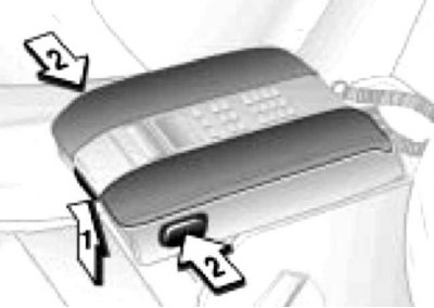
1. Front center armrest with built-in storage compartment can be moved forward and backward by pressing the button (1).
2. To open the glove compartment lid, press the buttons (2).
In addition to the storage boxes listed above, additional storage spaces for various items are available:
- In the inclined part of the center console;
- In the center console between the seats;
- Under each side of the phone (with appropriate equipment);
- Rotating coin compartment on the right under the audio system cover;
- In the doorway;
- On the backs of the front seats.
For ski transportation some models are equipped with a special bag, which can be accessed by folding down the central armrest of the rear seat.
First aid kit and warning triangle
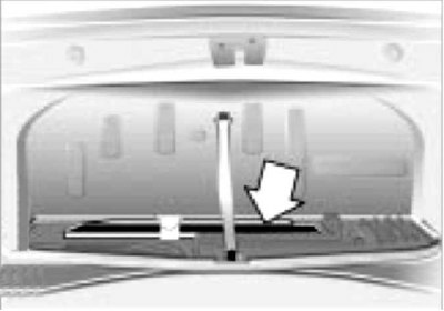
Warning triangle stored in the luggage compartment, in the tool holder.
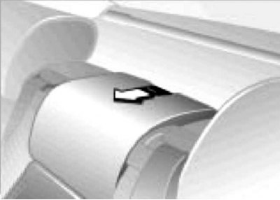
First aid kit stored between the rear seats. Pull the lever in the direction of the arrow.
This article is available at russian, bulgarian, belarusian, ukrainian, serbian, croatian, romanian, polish, slovak, hungarian
Article verified: Polikarpov Saveliy
Share information:
Previous articles
БМВ E38: Manual
Next articles
Similar articles on other types of BMW cars:
Body/interior equipment BMW 3 Series E36 (1990-2000)
Controls and instrumentation BMW 3 Series E21 (1975-1983)
Body / interior equipment BMW 5 Series E39 (1995-2003)
Controls and instrumentation BMW 5 Series E12 (1972-1981)
Controls BMW X3 E83 (2003-2010)
Controls and instrument panel BMW X5 E53 (1999-2006)
Link in different formats to this page
Visitor comments
No comments yet
- General information
- Introduction to guide
- Manual
- Maintenance
- Power unit
- Engine M60/1, M60/2 (petrol)
- M62 engine (petrol)
- M57 engine (diesel)
- M67 engine (diesel)
- Cooling system
- Fuel system (petrol)
- Fuel system (diesel)
- Exhaust system
- Ignition and control systems
- Charge and launch systems
- Transmission
- Clutch
- Mechanical gearbox
- Automatic gearbox
- Cardan and drive shafts
- Chassis
- Brake system
- Front suspension
- Rear suspension
- Steering
- Body
- Exterior
- Interior
- Electrical equipment
- Equipment and devices
- Lighting
- Heating and air conditioning
- Electrical circuits
- General information
- Care and maintenance
- Power unit
- Minor engine repair
- Engine overhaul
- Lubrication system
- Cooling system
- Ignition system
- Supply system
- Injection system (petrol)
- Injection system (diesel)
- Exhaust system
- Transmission
- Clutch
- Manual gearbox
- Automatic gearbox
- Cardan gear
- Rear axle and shafts
- Chassis
- Front suspension
- Rear suspension
- Steering
- Wheels and tires
- Brake system
- Body
- Body elements
- Electrical equipment
- Equipment and devices
- Electrical circuits