
Withdrawal
Below is a description using the example of AT A5S 310Z engine M60/1.
1. Disconnect the negative cable from the battery.
2. Remove the complete exhaust system and its heat shields (see chapter Power supply and exhaust systems).
3. Remove the mudguard mounting brackets on both sides.
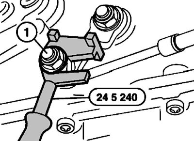
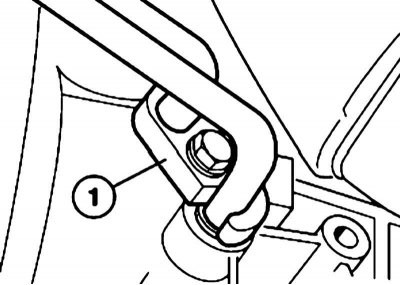
4. On models until 08.1995 issue. set the selector lever to the position «P» and install tool no. 24 5 240 on the balancer of the control box. Give the nut (1).
When installing, adjust the selector lever.
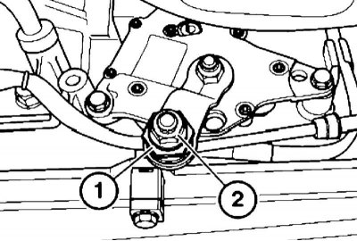
5. On models from 08.1995 issue. give the nut (2, holding the clamp (1).
When installing, adjust the selector lever.
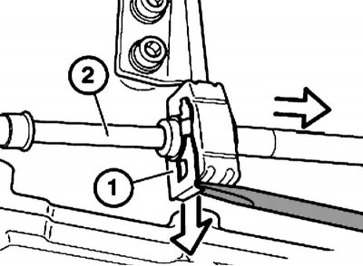
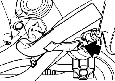
6. Remove the retainer with a screwdriver (1) and pull out the traction (2).
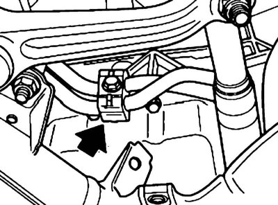
7. Remove the heat shield from the left side of the front axle beam. Disconnect the oil line brackets from the crankcase.
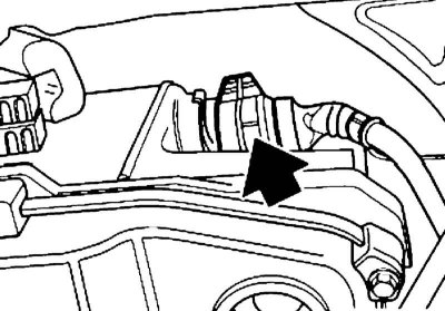
8. Substitute a container to collect the leaking oil, give the fasteners (1) and release the tips of the oil lines from the AT crankcase.
When assembling, use new O-rings for the oil lines.
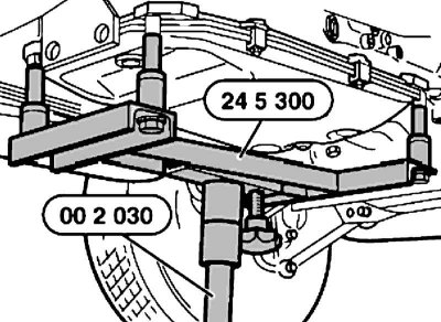
9. Support the AT with the help of special devices No. 00 2 030/24 5 300.
10. Disconnect the electrical wiring of the lambda probes from the transverse beam of the AT mount (see chapter Power supply and exhaust systems), turn out bolts of fastening and remove a transverse beam of fastening АТ.
11. Disconnect the cardan shaft from the AT and post it (see chapter Cardan and drive shafts, gearbox, differential and hub assemblies).
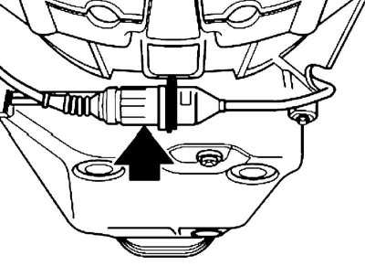
12. Separate connectors of electroconducting and take it from brackets of fastening to crankcase АТ.
13. Remove the plug.
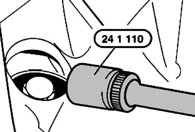
14. Using a special key No. 24 1 110, align 4 torque converter mounting bolts.
15. Turn out a bolt and take down a cover of a wire of a positive conclusion of the storage battery.
16. Insert tool (bar) No. 23 3 030 between the engine sump and the front axle beam.
17. Turn the front wheels to the left and lower the AT.
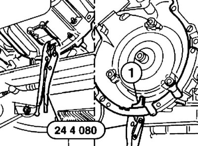
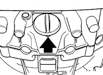
18. To prevent the torque converter from slipping, fix it relative to AT. To do this, insert tool no. 24 4 080 into the window (1) AT crankcase and hold the torque converter with it.
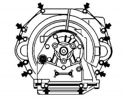
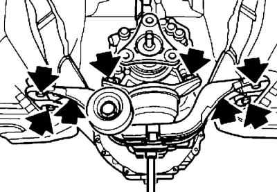
19. Turn out bolts of fastening of АТ, take away it back, pull out and lower АТ.
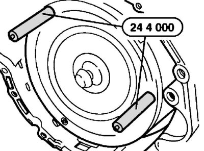
20. If necessary, remove the torque converter. To do this, screw into it adaptations No. 24 4 000 and remove the torque converter from the AT.
At the same time, ATF flows out.
Installation
1. Installation is carried out in the reverse order. Pay attention to the following points.
2. When installing the torque converter, be careful not to damage the O-ring and bearing. Insert the torque converter into the crankcase, apply slight pressure and rotate until the notches of the torque converter engage with the oil pump drive shaft. Push the torque converter in until it stops.
3. To screw bolts of fastening AT it is necessary only together with washers.
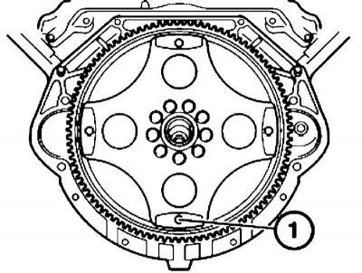
4. When installing AT, fixture No. 24 2 300 must be located coaxially with the holes in the compensating clutch, and through the window of the oil pan there must be access to the hole (1) compensating clutch. Screw tool no. 24 2 300 into the threaded hole and, if necessary, turn the torque converter until the hole is at the bottom.
5. Make sure that the centering sleeves are present. If necessary, remove the centering sleeves from the AT crankcase and insert into the cylinder block. Replace damaged centering sleeves.
6. Upon completion of work, check the ATF level and, if necessary, correct it (see chapter Vehicle settings and routine maintenance).