
Removal and installation an automatic transmission (A5 S360R/390 R) assembled
Attention: Check the oil level after completing the work.
Attention:
- Use only certified brands of transmission oil.
- Failure to comply with this rule will result in serious damage to the automatic transmission.
1. Disconnect the battery.
2. Remove the front panel of the engine auxiliary mechanisms protection.
3. Remove the stiffener plate.
4. Remove the exhaust system assembly.
5. Remove the heat-insulating screen.
6. Disconnect the front propeller shaft from the transfer case and lift it off the ground.
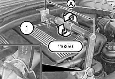
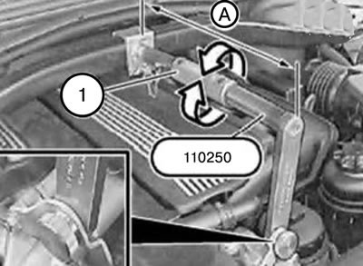
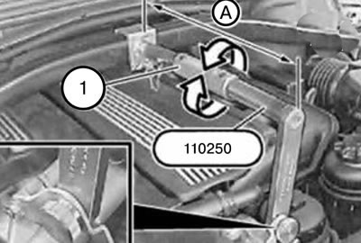
6. Install tool 110250 between the tensioner and the engine eye and secure it with a pin.
7. Using the coupling (1), create tension on the device by adjusting dimension A.
Size A: 36 cm.
8. Fix the engine in the mounting position.
9. Disconnect the propeller shaft from the gearbox.
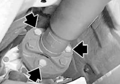
10. Unscrew the intermediate support.
11. Move the cardan shaft to the side and tie it up.
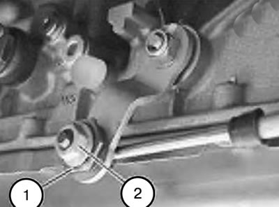
12. Holding the clamping sleeve (1), loosen the nut (2).
Tightening torque: 10 Nm.
Note: When installing, it is necessary to adjust the control unit balancer.
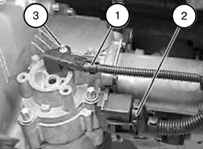
13. Remove the screws (1).
14. Remove the bracket together with the rod (2).
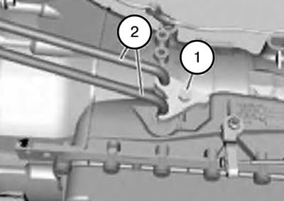
15. Unscrew the screw (1).
16. Disconnect the hydraulic lines (2) leading to the gearbox radiator.
Note: When installing, it is necessary to replace the sealing rings.
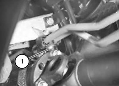
17. Loosen the screw (1) on the side member.
18. Move the hydraulic lines to the side.
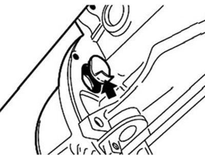
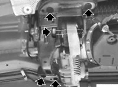
19. Hook and remove the plug.
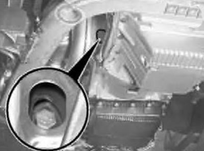
20. Turn the engine forward using the vibration damper until the screw appears in the hole.
21. Remove all torque converter screws using tool 241110.
22. Turning the engine further, unscrew two more screws.
Tightening torque:
- M10:45 Nm.
- M10 10.9:56 Nm.
Note: Take precautions against torque converter slippage.
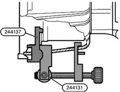
23. Insert tool 244131/244137 into the gearbox housing hole.
24. Clamp the torque converter.
Note: When connecting the engine and gearbox, remove tools 244131/244137.
25. Loosen the mounting screws and remove the gearbox mounting cross beam.
Tightening torque:
- Gearbox mounting beam to body mounting screws: 21 Nm.
- Gearbox mounting beam to rubber mount mounting screws: 73 Nm.
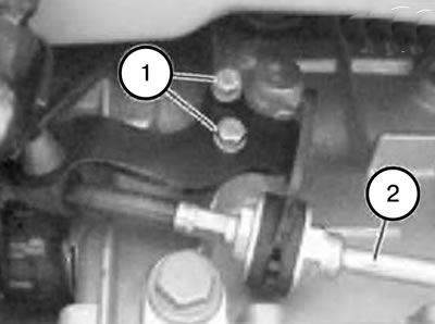
26. Disconnect connectors (1) and (2) from the servomotor.
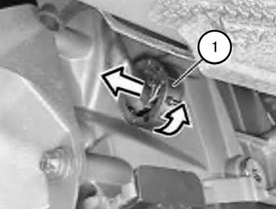
27. Unlock and disconnect the connector (1).
28. Release the cable from the clamps on the gearbox housing.
29. Using the coupling (1), set the tool 110250 back to dimension "A".
Size "A": 34 cm.
30. Bring the gearbox into the dismantling position.
Caution: When lowering the gearbox, ensure that the engine does not rest on the front shield.
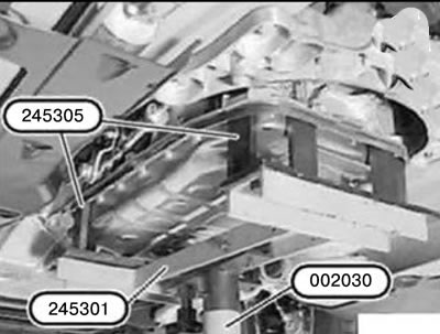
31. Support the gearbox with tools 002030/245301/245305.
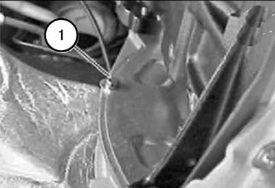
32. Unscrew the screw (1).
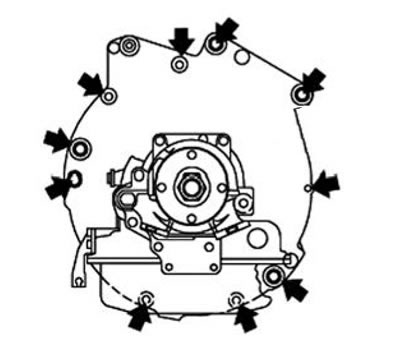
33. Remove the screws.
Tightening torque:
- M8: 24 Nm.
- M10:45 Nm.
- M12: 82 Nm.
34. Move the gearbox back away from the engine and lower it.
Note:
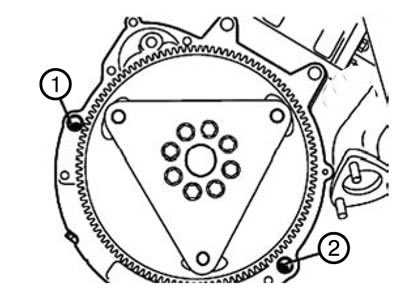
- When installing, it is necessary to check the correct installation of the centering bushings (1) and (2).
- Replace damaged centering bushings.
Caution: When connecting the engine and gearbox, ensure that nothing impedes the rotation of the torque converter.
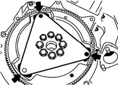
Note:
- The sheet metal flywheel has three tabs for the torque converter mounting plates.
- When connecting the engine and transmission, the three torque converter mounting plates must be aligned with the three sheet metal flywheel bosses.
- Failure to comply with this rule will result in damage to the gearbox.
- Once connected, it will be impossible to turn the torque converter or engine, which will lead to damage.
Note: Before installing the gearbox mounting cross member using the coupling (1), reinstall tool 110250 to dimension "A" (mounting position).
Size "A": 36 cm.
35. Install in the reverse order of removal, taking into account the above notes.