Attention! When performing operations to replace and adjust parts of the luggage door, it is necessary to avoid damage to adjacent parts.
After disconnecting the door support, make sure that the lower part of the door does not rest on the rear bumper.
When closing the door, the lock retainer should not hit or rub against its internal parts. Pay attention to the appearance of scratches.
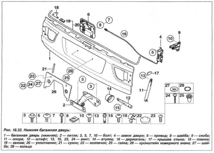
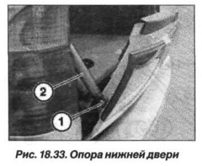
Remove the lower tailgate trim. Disconnect the electrical connections and pull the wiring harness out of the tailgate, first securing a nylon cord to its end. Open the door enough to expose the bolt (1, Fig. 18.33), since there is a risk of injury due to the spring force. In this position, unscrew the bolt (1) and leave it in the hole in the support (2) until installation.
Lift the front trim of the lower luggage door. Unscrew the bolts securing the door hinges and remove the lower luggage door.
The installation of the lower luggage door should be carried out in the reverse order, while it is necessary. Install the lower luggage door along the traces of the bolts on the hinge. In this case, there is no need for adjustment after its installation.
Before adjusting the lower part of the trunk lid, you should adjust the upper part.
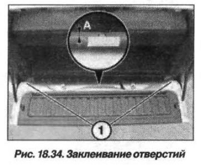
The lower luggage door must be adjusted in the following order. Completely seal the holes (1, Fig. 18.34) transparent adhesive tape. In this case, the middle hole is partially sealed (size "A" or = 1.0 mm to the seal).
Raise the front trim of the lower part of the luggage door, loosen the screws of the hinges on the door. Adjust the lower luggage door to the specified gap values. After adjustment, tighten the screws. When the hinges are moved further, unpainted surfaces become visible. They must be painted in the appropriate color.
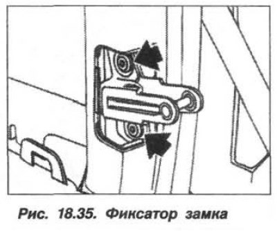
If necessary, loosen the screws (arrows, Fig. 18.35) on the side lock retainers. Adjust the lower trunk door so that when the door is closed, the retainers do not hit or rub against the internal parts of the locks.
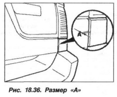
The lower tailgate should be flush with the rear wing, but may be deeper relative to it by dimension A = 1.0 mm (1, Fig. 18.36). Once the adjustment is complete, tighten the screws on the lock clamps.