



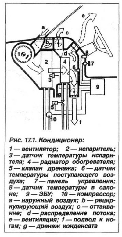
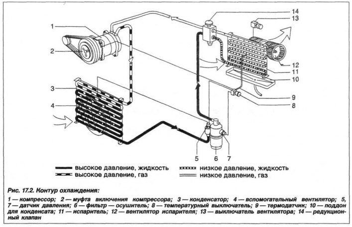
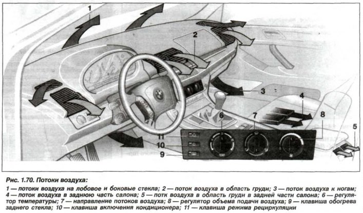
The general appearance of the vehicle air conditioning system is shown in Figure 17.1, the cooling circuit is shown in Figure 17.2, the air conditioner control unit is shown in Figure 1.70, the automatic air conditioner control unit and the direction of air flow are shown in Figure 1.70.
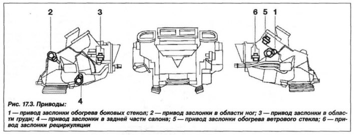
The arrangement of the heater/air conditioner unit drives is shown in Figure 17.3. When installing the drive, align the drive shaft of the corresponding flap relative to its drive shaft. The difference in the design between "Basis" and "High" is that the "High" system additionally has a solar sensor, a fogging sensor, an "AUC" system sensor, and a ventilation temperature sensor.
The control panels of the "Basis" and "High" systems are shown in Figures 1.70 and 17.21, respectively.
(The article was copied from an online resource «BMWman»)