
Table of contents: Fasteners ↓ Fastener size ↓
- Home
- BMW X5
- E53
- General information
- Maintenance
- General requirements for car repair
General requirements for car repair (BMW X5 E53)
The majority of malfunctions of mechanical units and assemblies during operation occur as a result of friction processes, deformation of elements, aging of materials of parts, etc. These and other processes entail wear and tear and damage of parts.
The wear process is usually divided into three periods: running-in; normal wear and tear; emergency.
During the running-in process, there is intensive wear of the rubbing parts, as a result of which the micro-roughness of the mating surfaces decreases, the contact area increases, the specific loads decrease, the wear rate slows down and turns into normal wear.
The period of normal wear is characterized by a relatively small rate of growth of the gap in the coupling, however, upon reaching a certain gap, the wear rate increases sharply, which indicates the onset of emergency wear. Operation of the unit with emergency wear leads to breakdowns that cannot be repaired.
During operation, it is very important to repair the unit before emergency wear occurs. In this case, the repair costs will be significantly lower than when repairing a unit with emergency wear. Before making a decision on repair, it is necessary to diagnose the condition of the coupling in the units. As a rule, diagnostics are carried out based on indirect signs, such as: increased noise, vibration, oil consumption, crankcase gas breakthrough, power loss, etc. For better diagnostics, the unit must be disassembled, the parts washed, inspected and subjected to micrometric analysis.
Based on the results of inspection and measurements, a decision is made to continue operation without repair or to determine repair. In this case, the following considerations should be followed: if the actual dimensions of the parts are within the tolerance fields permitted by this Manual, then continued operation of the unit without repair is possible; if the dimensions are outside the tolerance range, then repairs are required.
The extension of tolerance fields given in this Manual should be regarded as an opportunity to use the residual resource of the unit without restoring the coupling. In case of repair of the unit during the restoration of couplings, the extension of tolerance fields beyond the established ones is not allowed.
The repair technology is usually divided into four stages of work: disassembly - washing; control - sorting; repair itself: restoration of micro and macro geometry of parts surfaces and their physical and mechanical properties; assembly with preliminary inspection of parts entering work.
Disassembly and washing operations are carried out in several stages: external washing of the unit, partial disassembly, unit washing, disassembly into parts, washing and cleaning of parts. All parts before inspection and sorting must be thoroughly cleaned from dirt and carbon deposits, degreased, washed and dried (compressed dry air). Clean oil channels and holes in parts, flush under pressure and blow out with compressed air.
Parts made of aluminum and zinc alloys must not be washed in alkaline solutions used for washing steel and cast iron parts, since aluminum and zinc dissolve in alkalis.
During the inspection of parts, breaks, cracks, dents, cavities and other damages are detected by visual inspection. The presence of cracks in critical parts is checked using a flaw detector. The dimensions of parts must be checked in places of greatest wear. Gear teeth wear unevenly, therefore, when inspecting them, at least three teeth located at an angle of 120° must be measured.
Due to the need to guarantee the operation of gear transmissions during the entire period between repairs, chipping of teeth and flaking of the working surface of teeth due to fatigue are not permitted.
Assembly units such as: connecting rod with connecting rod cap, cylinder block with main bearing caps, gearbox gears and final drive gears cannot be disassembled. Other assembly units can be disassembled, but if a decision is made to continue operating the mating elements without repair, then it is not advisable to disassemble them.
In all cases of repair by welding and surfacing, the weld seam must not have slag inclusions, unchecked areas, undercuts and other defects. Clean the seam after welding. Remove metal burrs so that they do not interfere with the installation of the mating parts.
Holes with worn or damaged threads are restored by cutting a thread of an increased repair size, or by welding the holes and then cutting a thread of the nominal size. By installing inserts and spiral threaded inserts.
The use of threaded inserts is preferable for reasons of restoration quality and labor costs. The parts supplied for assembly must be clean and dry. The threaded connections must have no defects. Disposable self-locking threaded fasteners must be replaced with new ones. If it is impossible to use new self-locking parts, when installing the old ones, they must be locked from unscrewing.
When assembling, install new gaskets and seals. Lubricate the rubbing surfaces of the parts with clean oil during assembly. When installing rubber seals, lubricate the working surface of the cuff to avoid damage during installation. When installing seals with a metal body, lubricate the seat under the seal with a thin layer of sealant.
Assemble units and assemblies in accordance with this Manual. Use a measuring instrument to check the dimensions of the parts forming the fits before assembly.
When assembling parts that have a movable fit in the mating, their free relative movement must be ensured, without jamming. Bushings, rings of ball and roller bearings must be installed using mandrels. When pressing in bearings, the force must not be transmitted through the balls or rollers. Pressing tools must rest against the pressed ring. Pressing forces must coincide with the bearing axis to avoid distortion of the rings.
If, according to the assembly conditions, the installation of critical parts is carried out by hammer blows, it is necessary to use mandrels and hammers made of non-ferrous metals, plastic, rubber, as well as devices and gaskets for pressing in parts.
The keys must be tightly seated in the shaft keyways using a hammer or a non-ferrous metal mandrel. No play in the keys in the shaft keyways is allowed.
The studs must be screwed into dry and clean threaded holes tightly without any play. The parts must be put on the studs freely. Bending the studs when installing parts on them is not allowed, the fastening of the unit or part with several nuts or bolts must be done evenly along the perimeter - first preliminary, and then finally.
All nuts or bolts of a joint must be tightened to the same torque unless otherwise specified, as per Appendix. Tightening torques for fasteners are given in the Appendix to this Manual, and wrenches capable of limiting the torque must be used.
The list below includes the minimum of standard tools required to perform operations on removal, disassembly, repair, assembly and installation of vehicle components and assemblies:
To perform high-quality repair operations, it is also necessary to have special tools and devices:
Fasteners are a set consisting of nuts, bolts, studs, rivets, washers and locking elements, designed to connect two or more parts. Connections can be detachable, the main type is threaded, and non-detachable - riveted and welded. All installed threaded fasteners must be clean, straight, with undamaged threads and strict edges of the bolt and nut heads, on which the wrench heads are installed.
Special self-locking nuts with nylon and fiber inserts cannot be reused and are replaced with new ones.
Rusted bolts and nuts are pre-treated with a penetrating compound, such as turpentine, kerosene or special liquids, to facilitate removal, and then left to stand for a while before unscrewing. In emergency cases, it is permissible to use a chisel or hacksaw, followed by removing the remains of the fastener from the threaded part. Flat (lining) and lock washers during assembly must always be installed in place in the same order and in the same way as during disassembly and removal.
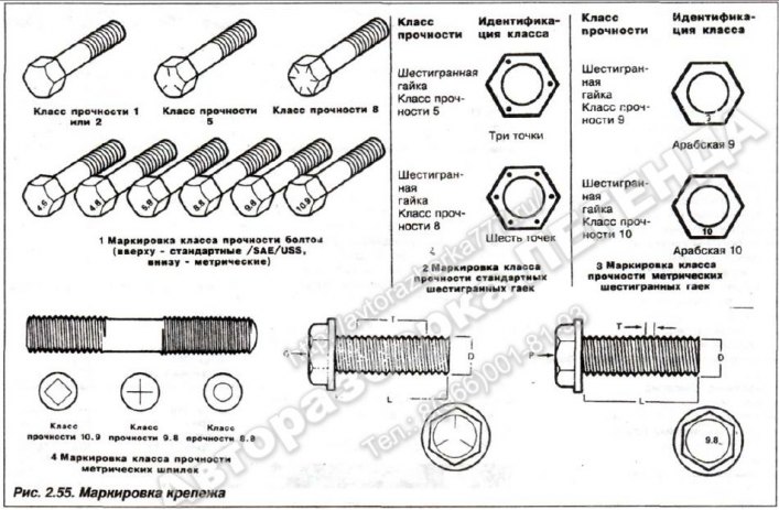
When assembling a car, fastening elements made according to the inch system of measurements are used (english system or SAE standard), and the more universal one - the metric system of measures. Despite all their similarities, it is unacceptable to confuse them (Fig. 2.55).
Both metric and standard bolts can be identified by inspecting the heads.
The tightening torques of threaded connections provided by BMW-AG, if they are not specifically specified in the technical specifications, are determined depending on the thread diameter.
The bolt threads should protrude from the nut (except in specially specified cases) on 2-3 threads. The cotter pins should not protrude from the nut slots. The ends of the cotter pins should be spread apart and bent, one onto the bolt and the other onto the nut. When assembling, blow out the fuel line and brake system drive tubes with compressed air and roll them with a ball of the appropriate diameter. Damaged threads in the side members and other fastening elements may be repaired using threaded inserts made of wire spiral (Fig. 2.56) in the following order:
The wear process is usually divided into three periods: running-in; normal wear and tear; emergency.
During the running-in process, there is intensive wear of the rubbing parts, as a result of which the micro-roughness of the mating surfaces decreases, the contact area increases, the specific loads decrease, the wear rate slows down and turns into normal wear.
The period of normal wear is characterized by a relatively small rate of growth of the gap in the coupling, however, upon reaching a certain gap, the wear rate increases sharply, which indicates the onset of emergency wear. Operation of the unit with emergency wear leads to breakdowns that cannot be repaired.
During operation, it is very important to repair the unit before emergency wear occurs. In this case, the repair costs will be significantly lower than when repairing a unit with emergency wear. Before making a decision on repair, it is necessary to diagnose the condition of the coupling in the units. As a rule, diagnostics are carried out based on indirect signs, such as: increased noise, vibration, oil consumption, crankcase gas breakthrough, power loss, etc. For better diagnostics, the unit must be disassembled, the parts washed, inspected and subjected to micrometric analysis.
Based on the results of inspection and measurements, a decision is made to continue operation without repair or to determine repair. In this case, the following considerations should be followed: if the actual dimensions of the parts are within the tolerance fields permitted by this Manual, then continued operation of the unit without repair is possible; if the dimensions are outside the tolerance range, then repairs are required.
The extension of tolerance fields given in this Manual should be regarded as an opportunity to use the residual resource of the unit without restoring the coupling. In case of repair of the unit during the restoration of couplings, the extension of tolerance fields beyond the established ones is not allowed.
The repair technology is usually divided into four stages of work: disassembly - washing; control - sorting; repair itself: restoration of micro and macro geometry of parts surfaces and their physical and mechanical properties; assembly with preliminary inspection of parts entering work.
Disassembly and washing operations are carried out in several stages: external washing of the unit, partial disassembly, unit washing, disassembly into parts, washing and cleaning of parts. All parts before inspection and sorting must be thoroughly cleaned from dirt and carbon deposits, degreased, washed and dried (compressed dry air). Clean oil channels and holes in parts, flush under pressure and blow out with compressed air.
Parts made of aluminum and zinc alloys must not be washed in alkaline solutions used for washing steel and cast iron parts, since aluminum and zinc dissolve in alkalis.
During the inspection of parts, breaks, cracks, dents, cavities and other damages are detected by visual inspection. The presence of cracks in critical parts is checked using a flaw detector. The dimensions of parts must be checked in places of greatest wear. Gear teeth wear unevenly, therefore, when inspecting them, at least three teeth located at an angle of 120° must be measured.
Due to the need to guarantee the operation of gear transmissions during the entire period between repairs, chipping of teeth and flaking of the working surface of teeth due to fatigue are not permitted.
Assembly units such as: connecting rod with connecting rod cap, cylinder block with main bearing caps, gearbox gears and final drive gears cannot be disassembled. Other assembly units can be disassembled, but if a decision is made to continue operating the mating elements without repair, then it is not advisable to disassemble them.
In all cases of repair by welding and surfacing, the weld seam must not have slag inclusions, unchecked areas, undercuts and other defects. Clean the seam after welding. Remove metal burrs so that they do not interfere with the installation of the mating parts.
Holes with worn or damaged threads are restored by cutting a thread of an increased repair size, or by welding the holes and then cutting a thread of the nominal size. By installing inserts and spiral threaded inserts.
The use of threaded inserts is preferable for reasons of restoration quality and labor costs. The parts supplied for assembly must be clean and dry. The threaded connections must have no defects. Disposable self-locking threaded fasteners must be replaced with new ones. If it is impossible to use new self-locking parts, when installing the old ones, they must be locked from unscrewing.
When assembling, install new gaskets and seals. Lubricate the rubbing surfaces of the parts with clean oil during assembly. When installing rubber seals, lubricate the working surface of the cuff to avoid damage during installation. When installing seals with a metal body, lubricate the seat under the seal with a thin layer of sealant.
Assemble units and assemblies in accordance with this Manual. Use a measuring instrument to check the dimensions of the parts forming the fits before assembly.
When assembling parts that have a movable fit in the mating, their free relative movement must be ensured, without jamming. Bushings, rings of ball and roller bearings must be installed using mandrels. When pressing in bearings, the force must not be transmitted through the balls or rollers. Pressing tools must rest against the pressed ring. Pressing forces must coincide with the bearing axis to avoid distortion of the rings.
If, according to the assembly conditions, the installation of critical parts is carried out by hammer blows, it is necessary to use mandrels and hammers made of non-ferrous metals, plastic, rubber, as well as devices and gaskets for pressing in parts.
The keys must be tightly seated in the shaft keyways using a hammer or a non-ferrous metal mandrel. No play in the keys in the shaft keyways is allowed.
The studs must be screwed into dry and clean threaded holes tightly without any play. The parts must be put on the studs freely. Bending the studs when installing parts on them is not allowed, the fastening of the unit or part with several nuts or bolts must be done evenly along the perimeter - first preliminary, and then finally.
All nuts or bolts of a joint must be tightened to the same torque unless otherwise specified, as per Appendix. Tightening torques for fasteners are given in the Appendix to this Manual, and wrenches capable of limiting the torque must be used.
The list below includes the minimum of standard tools required to perform operations on removal, disassembly, repair, assembly and installation of vehicle components and assemblies:
- set of combination wrenches (1/4-1 inch, 6-19 mm);
- set of replacement socket heads (1/4-1 inch, 6-19 mm);
- ratchet reversible drive with handle (250 mm);
- universal joint cardan type for socket heads;
- torque wrench;
- machinist's hammer (250-300 g);
- mallet (wood, rubber or plastic);
- set of adjustable wrenches;
- set of external socket wrenches;
- spark plug wrench;
- spark plug gap adjuster;
- set of measuring probes;
- brake bleeder key;
- screwdrivers ("-" 8x150 mm. 8.5x150 mm; "+" 2x6x150 mm, 3x8x203 mm);
- combination pliers;
- clamping pliers;
- dielectric pliers;
- duckbill pliers;
- chisel (13 mm);
- hacksaw with a set of blades;
- set of files;
- tire pressure gauge; grease gun;
- non-ferrous metal scraper;
- oil filter wrench;
- metalworking scriber;
- center punch;
- beards (1.8; 3,3; 4.8 mm);
- steel ruler-bar;
- set of supports;
- jack,
- 3/8-inch (9 mm) electric drill and drill set;
- fine sandpaper;
- wire brush (big and small);
- oil container;
- container for antifreeze;
- pouring funnel.
To perform high-quality repair operations, it is also necessary to have special tools and devices:
- for compressing valve springs;
- for cleaning piston ring grooves;
- for compressing piston rings;
- for removing/installing piston rings;
- for centering the clutch disc;
- to remove the steering wheel damper;
- for removing brake shoe spring caps;
- compression meter;
- countersink and hone for processing the edge and mirror of the cylinder;
- hone for processing the brake cylinder mirror;
- cylinder diameter meter (nutrometer);
- a set of micrometers and a caliper;
- hydraulic tappet removal tool;
- universal puller;
- ball joint puller;
- impact screwdriver;
- strobe with adapter;
- hand combination pump (vacuum/pressure);
- tachometer;
- tester;
- set of taps and dies;
- lifting rigging;
- brake spring removal tools;
- floor garage jack. A complete list of special devices and their purpose is given in the Appendix to this Manual.
Fasteners
Fasteners are a set consisting of nuts, bolts, studs, rivets, washers and locking elements, designed to connect two or more parts. Connections can be detachable, the main type is threaded, and non-detachable - riveted and welded. All installed threaded fasteners must be clean, straight, with undamaged threads and strict edges of the bolt and nut heads, on which the wrench heads are installed.
Special self-locking nuts with nylon and fiber inserts cannot be reused and are replaced with new ones.
Attention! Damaged fastening elements (nuts, bolts, studs, washers) are subject to mandatory replacement.
Rusted bolts and nuts are pre-treated with a penetrating compound, such as turpentine, kerosene or special liquids, to facilitate removal, and then left to stand for a while before unscrewing. In emergency cases, it is permissible to use a chisel or hacksaw, followed by removing the remains of the fastener from the threaded part. Flat (lining) and lock washers during assembly must always be installed in place in the same order and in the same way as during disassembly and removal.
Fastener size
When assembling a car, fastening elements made according to the inch system of measurements are used (english system or SAE standard), and the more universal one - the metric system of measures. Despite all their similarities, it is unacceptable to confuse them (Fig. 2.55).
Both metric and standard bolts can be identified by inspecting the heads.
The tightening torques of threaded connections provided by BMW-AG, if they are not specifically specified in the technical specifications, are determined depending on the thread diameter.
Attention! Below are the data on the maximum permissible tightening torque of standard threaded connections depending on the thread size, the material of the bolt, screw, nut, etc., the color of its surface coating and the strength class, as set out in the internal BMW standard No.600.02.0.
| Maximum tightening torque for connections with M4 thread: | ||
| - yellow (ZN) | (8,8) | 2.9 Nm; |
| - silver (ZNS) | (8,8) | 2.4 Nm; |
| - yellow (ZN) | (10,9) | 4.1 Nm; |
| - silver (ZNS) | (10,9) | 3.6 Nm; |
| - yellow (ZN) | (12,9) | 4.9 Nm. |
| Maximum tightening torque for connections with M5 thread: | ||
| - yellow (ZN) | (8,8) | 5.9 Nm; |
| - silver (ZNS) | (8,8) | 5.0 Nm; |
| - yellow (ZN) | (10,9) | 8.3 Nm; |
| - silver (ZNS) | (10,9) | 7.3 Nm; |
| - yellow (ZN) | (12,9) | 10.0 Nm; |
| - silver (ZNS) | (12,9) | 8.0 Nm. |
| Maximum tightening torque for connections with M6 thread: | ||
| - yellow (ZN) | (8,8) | 9.9 Nm; |
| - silver (ZNS) | (8,8) | 8.6 Nm; |
| - yellow (ZN) | (10,9) | 14.0 Nm; |
| - silver (ZNS) | (10,9) | 12.6 Nm; |
| - yellow (ZN) | (12,9) | 16.5 Nm; |
| - silver (ZNS) | (12,9) | 14.0 Nm. |
| Maximum tightening torque for connections with M7 thread: | ||
| - yellow (ZN) | (8,8) | 14.8 Nm; |
| - silver (ZNS) | (8,8) | 14.0 Nm; |
| - yellow (ZN) | (10,9) | 21.3 Nm; |
| - silver (ZNS) | (10,9) | 20.5 Nm; |
| - yellow (ZN) | (12,9) | 25.5 Nm; |
| - silver (ZNS) | (12,9) | 22.5 Nm. |
| Maximum tightening torque for connections with M8 thread: | ||
| - yellow (ZN) | (8,8) | 24.0 Nm; |
| - silver (ZNS) | (8,8) | 20.5 Nm; |
| - yellow (ZN) | (10,9) | 34.0 Nm; |
| - silver (ZNS) | (10,9) | 30.5 Nm; |
| - yellow (ZN) | (12,9) | 40.0 Nm; |
| - silver (ZNS) | (12,9) | 33.5 Nm. |
| Maximum tightening torque for connections with M8x1 thread: | ||
| - yellow (ZN) | (8,8) | 26.0 Nm; |
| - silver (ZNS) | (8,8) | 22.0 Nm; |
| - yellow (ZN) | (10,9) | 36.0 Nm; |
| - silver (ZNS) | (10,9) | 32.0 Nm; |
| - yellow (ZN) | (12,9) | 44.0 Nm; |
| - silver (ZNS) | (12,9) | 35.5 Nm. |
| Maximum tightening torque for connections with M10 thread: | ||
| - yellow (ZN) | (8,8) | 47.0 Nm; |
| - silver (ZNS) | (8,8) | 41.0 Nm; |
| - yellow (ZN) | (10,9) | 66.0 Nm; |
| - silver (ZNS) | (10,9) | 60.0 Nm; |
| - yellow (ZN) | (12,9) | 79.0 Nm; |
| - silver (ZNS) | (12,9) | 66.0 Nm. |
| Maximum tightening torque for connections with M10x1 thread: | ||
| - yellow (ZN) | (8,8) | 54.0 Nm; |
| - silver (ZNS) | (8,8) | 44.0 Nm; |
| - yellow (ZN) | (10,9) | 75.0 Nm; |
| - silver (ZNS) | (10,9) | 65.0 Nm; |
| - yellow (ZN) | (12,9) | 91.0 Nm; |
| - silver (ZNS) | (12,9) | 72.0 Nm. |
| Maximum tightening torque for connections with M12 thread: | ||
| - yellow (ZN) | (8,8) | 82.0 Nm; |
| - silver (ZNS) | (8,8) | 71.0 Nm; |
| - yellow (ZN) | (10,9) | 115.0 Nm; |
| - silver (ZNS) | (10,9) | 104.0 Nm; |
| - yellow (ZN) | (12,9) | 140.0 Nm; |
| - silver (ZNS) | (12,9) | 116.0 Nm. |
| Maximum tightening torque for connections with M12x1.5 thread: | ||
| - yellow (ZN) | (8,8) | 87.0 Nm; |
| - silver (ZNS) | (8,8) | 73.0 Nm; |
| - yellow (ZN) | (10,9) | 123.0 Nm; |
| - silver (ZNS) | (10,9) | 108.0 Nm; |
| - yellow (ZN) | (12,9) | 147.0 Nm; |
| - silver (ZNS) | (12,9) | 120.0 Nm. |
| Maximum tightening torque for connections with M14 thread: | ||
| - yellow (ZN) | (8,8) | 130.0 Nm; |
| - silver (ZNS) | (8,8) | 112.0 Nm; |
| - yellow (ZN) | (10,9) | 180.0 Nm; |
| - silver (ZNS) | (10,9) | 165.0 Nm; |
| - yellow (ZN) | (12,9) | 220.0 Nm; |
| - silver (ZNS) | (12,9) | 185.0 Nm. |
| Maximum tightening torque for connections with M14x1.5 thread: | ||
| - yellow (ZN) | (8,8) | 143.0 Nm; |
| - silver (ZNS) | (8,8) | 120.0 Nm; |
| - yellow (ZN) | (10,9) | 200.0 Nm; |
| - silver (ZNS) | (10,9) | 175.0 Nm; |
| - yellow (ZN) | (12,9) | 240.0 Nm; |
| - silver (ZNS) | (12,9) | 195.0 Nm. |
| Maximum tightening torque for connections with M18 thread: | ||
| - yellow (ZN) | (8,8) | 280.0 Nm; |
| - silver (ZNS) | (8,8) | 240.0 Nm; |
| - yellow (ZN) | (10,9) | 390.0 Nm; |
| - silver (ZNS) | (10,9) | 355.0 Nm; |
| - yellow (ZN) | (12,9) | 470.0 Nm; |
| - silver (ZNS) | (12,9) | 395.0 Nm. |
| Maximum tightening torque for connections with M18x1.5 thread: | ||
| - yellow (ZN) | (8,8) | 313.0 Nm; |
| - silver (ZNS) | (8,8) | 265.0 Nm; |
| - yellow (ZN) | (10,9) | 440.0 Nm; |
| - silver (ZNS) | (10,9) | 385.0 Nm; |
| - yellow (ZN) | (12,9) | 527.0 Nm; |
| - silver (ZNS) | (12,9) | 430.0 Nm. |
The bolt threads should protrude from the nut (except in specially specified cases) on 2-3 threads. The cotter pins should not protrude from the nut slots. The ends of the cotter pins should be spread apart and bent, one onto the bolt and the other onto the nut. When assembling, blow out the fuel line and brake system drive tubes with compressed air and roll them with a ball of the appropriate diameter. Damaged threads in the side members and other fastening elements may be repaired using threaded inserts made of wire spiral (Fig. 2.56) in the following order:
- drill out the remains of the old bolt (stud);
- cut threads for wire insert;
- select the insert and screw it into the hole flush;
- break off and remove the tail of the insert.
This article is available at russian, bulgarian, belarusian, ukrainian, serbian, croatian, romanian, polish, slovak, hungarian
Article verified: Zhuravleva Isolda
Share information:
Previous articles
БМВ E53: Maintenance
Next articles
Similar articles on other types of BMW cars:
Cylinder head repair BMW 3 Series E21 (1975-1983)
Gearbox. General information BMW 3 Series E30 (1982-1994)
Engine Repair Manual. General Information BMW 5 Series E34 (1988-1996)
General information about engine repair without removing it from the… BMW 5 Series E28 (1981-1988)
General preparation for engine repair BMW 7 Series E32 (1986-1994)
Introduction to the Automotive Repair Manual BMW X3 E83 (2003-2010)
Link in different formats to this page
Visitor comments
No comments yet
- General information
- Manual
- Maintenance
- M54 petrol engine
- Engine repair
- Lubrication system
- Cooling system
- Supply system
- Injection system
- Exhaust system
- Engine electrics
- M62 petrol engine
- Engine repair
- Lubrication system
- Cooling system
- Supply system
- Exhaust system
- Engine electrics
- N62 petrol engine
- Engine repair
- Cooling and lubrication system
- Power and exhaust system
- Engine electrics
- Diesel engine M57
- Engine repair
- Lubrication system
- Cooling system
- Power and exhaust system
- Engine electrics
- Turbocharging system
- Transmission
- Clutch
- Mechanical gearbox
- Automatic gearbox
- Transfer case and cardan
- Chassis
- Brake system
- Steering
- Front suspension
- Rear suspension
- Wheels and tires
- Body
- Exterior
- Interior
- Doors and windows
- Repair and maintenance
- Heater and air conditioner
- Electrical equipment
- Equipment and devices
- Levers and switches
- Electrical circuits