
- Home
- BMW X5
- E53
- Diesel engine M57
- Engine repair
- Crankshaft and flywheel — design description
Crankshaft and flywheel — design description (BMW X5 E53)
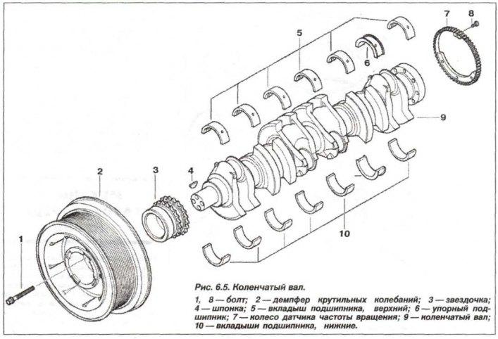
The engine crankshaft is a seven-bearing, cast iron with spheroidal graphite. The bearings are made in the body of the cylinder block crankcase in the form of plain bearings. Lubricating grooves are made in the upper liners of the main bearings. Counterweights are made on the cheeks of the shaft, cast together with the shafts. The crankshafts are divided into three size groups, marked with colored paint marks (yellow, green and white) on the cheeks, in the area of the molar necks.
The design of the crankshaft is shown in Figure 6.5.
Crankshaft main journal diameter:
yellow mark
green mark
white mark
Crankshaft axial clearance, when measured at the center support:
Radial clearance of crankshaft main bearings:
Diameter of crankshaft connecting rod journals:
Radial clearance of crankshaft connecting rod bearings:
The maximum permissible ovality of the surfaces of the main and connecting rod journals is no more than 0.003 mm.
The main and connecting rod bearing shells are bimetallic three-layer.
Radial clearance between bearing shells and crankshaft main/connecting rod journals:
The permissible runout of the middle journal of the crankshaft, installed on prisms, is no more than 0.15 mm.
Thrust bearing size:
If the clearances are greater than the maximum allowable, the bearing liners on the crankshaft journals must be replaced. If the crankshaft journals are worn, they must be ground to the nearest repair size, and the liners must be replaced with repair ones (increased thickness).
The flywheel is attached to the crankshaft flange with eight bolts. After removing the flywheel, replace the bolts with new ones, having previously applied a locking compound to their threaded part. Due to the presence of a centering pin, the flywheel is installed in only one position. The starter ring gear, before pressing onto the flywheel, is heated to a temperature of 220–250°C. Each time, tighten the new flywheel mounting bolts with a torque of:
The permissible runout of the flywheel, when measured along the outer circumference, is no more than 0.40 mm.
The design of the torsional vibration damper (2) is shown in Figure 6.5.
It has a diameter of 235 mm. The color of the marking is black. The permissible axial runout is no more than 0.30 mm. The permissible ovality is no more than 0.20 mm.
Fastening is carried out each time with new bolts (1) of the Torx type – M10x86 (4 pcs.), in three steps – with a torque of 40 Nm + 60° + 60°.
(The original version is on the portal BMWman.ru)
The design of the crankshaft is shown in Figure 6.5.
Crankshaft journal diameter
Crankshaft main journal diameter:
yellow mark
- nominal size - 59.977 - 59.983 mm
- size 1st class - 59.727 - 59.733 mm (reduction by 0.25 mm)
- size 2nd class - 59.477 - 59.483 mm (decrease by 0.50 mm)
green mark
- nominal size - 59.970 - 59.976 mm
- size 1st class - 59.720 - 59.726 mm (reduction by 0.25 mm)
- size 2nd class - 59.470 - 59.476 mm (decrease by 0.50 mm)
white mark
- nominal size - 59.964 - 59.969 mm
- size 1st class - 59.714 - 59.719 mm (reduction by 0.25 mm)
- size 2nd class - 59.464-59.469 mm (decrease by 0.50 mm)
Crankshaft axial clearance, when measured at the center support:
- nominal - 0.080 mm;
- maximum - 0.234 mm.
Radial clearance of crankshaft main bearings:
- nominal - 0.019 mm;
- maximum - 0.052 mm.
Diameter of crankshaft connecting rod journals
Diameter of crankshaft connecting rod journals:
- nominal size - 44.975 - 44.991 mm;
- 1st repair size - 44.725 - 44.741 mm;
- 2nd repair size - 44.475 - 44.491 mm.
Radial clearance of crankshaft connecting rod bearings:
- nominal - 0.020 mm;
- maximum - 0.055 mm.
The maximum permissible ovality of the surfaces of the main and connecting rod journals is no more than 0.003 mm.
Crankshaft bearing shells
The main and connecting rod bearing shells are bimetallic three-layer.
Radial clearance between bearing shells and crankshaft main/connecting rod journals:
- nominal - 0.020 mm
- maximum permissible - 0.055 mm.
The permissible runout of the middle journal of the crankshaft, installed on prisms, is no more than 0.15 mm.
Thrust bearing size:
- nominal width - 25.0 mm;
- 1st repair size - 25.2 mm;
- 2nd repair size - 25.4 mm;
- tolerance from +0.053 to +0.020 mm.
If the clearances are greater than the maximum allowable, the bearing liners on the crankshaft journals must be replaced. If the crankshaft journals are worn, they must be ground to the nearest repair size, and the liners must be replaced with repair ones (increased thickness).
Flywheel
The flywheel is attached to the crankshaft flange with eight bolts. After removing the flywheel, replace the bolts with new ones, having previously applied a locking compound to their threaded part. Due to the presence of a centering pin, the flywheel is installed in only one position. The starter ring gear, before pressing onto the flywheel, is heated to a temperature of 220–250°C. Each time, tighten the new flywheel mounting bolts with a torque of:
- under manual transmission — 105 N·m (10.5 kgf·m);
- under automatic transmission - 120 Nm (12.0 kgf·m).
The permissible runout of the flywheel, when measured along the outer circumference, is no more than 0.40 mm.
Torsional vibration damper
The design of the torsional vibration damper (2) is shown in Figure 6.5.
It has a diameter of 235 mm. The color of the marking is black. The permissible axial runout is no more than 0.30 mm. The permissible ovality is no more than 0.20 mm.
Fastening is carried out each time with new bolts (1) of the Torx type – M10x86 (4 pcs.), in three steps – with a torque of 40 Nm + 60° + 60°.
(The original version is on the portal BMWman.ru)
This article is available at russian, bulgarian, belarusian, ukrainian, serbian, croatian, romanian, polish, slovak, hungarian
Article verified: Zhuravleva Isolda
Share information:
Previous articles
БМВ E53: Engine repair
Next articles
Similar articles on other types of BMW cars:
Installing the crankshaft BMW 3 Series E21 (1975-1983)
Drum brake design BMW 3 Series E36 (1990-2000)
Installing the crankshaft BMW 5 Series E12 (1972-1981)
Engine power supply system — general information and design BMW 5 Series E34 (1988-1996)
General description of the car BMW 7 Series E32 (1986-1994)
Fuses — general description BMW X3 E83 (2003-2010)
Link in different formats to this page
Visitor comments
No comments yet
- General information
- Manual
- Maintenance
- M54 petrol engine
- Engine repair
- Lubrication system
- Cooling system
- Supply system
- Injection system
- Exhaust system
- Engine electrics
- M62 petrol engine
- Engine repair
- Lubrication system
- Cooling system
- Supply system
- Exhaust system
- Engine electrics
- N62 petrol engine
- Engine repair
- Cooling and lubrication system
- Power and exhaust system
- Engine electrics
- Diesel engine M57
- Engine repair
- Lubrication system
- Cooling system
- Power and exhaust system
- Engine electrics
- Turbocharging system
- Transmission
- Clutch
- Mechanical gearbox
- Automatic gearbox
- Transfer case and cardan
- Chassis
- Brake system
- Steering
- Front suspension
- Rear suspension
- Wheels and tires
- Body
- Exterior
- Interior
- Doors and windows
- Repair and maintenance
- Heater and air conditioner
- Electrical equipment
- Equipment and devices
- Levers and switches
- Electrical circuits