
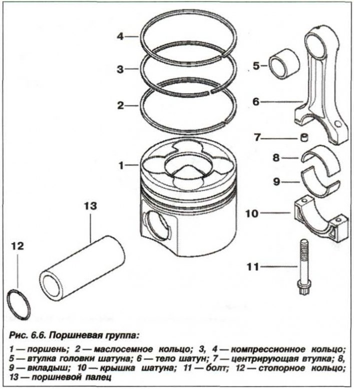
Pistons (1) made of aluminum alloy (hypereutectic silumin) with steel inserts. Each piston has two compression rings and one oil scraper ring. For the correct orientation of the piston when installed in the cylinder, there is an arrow on its bottom, which must be turned towards the camshaft drive, as well as a mark indicating its diameter. The piston diameter is measured at a distance «A» from the lower edge of the piston skirt at an angle of 90°relative to the axis of the piston pin. The piston parameters are shown below.
Piston diameter
Piston diameter:
- nominal - 83.950 mm;
- intermediate - 84.030 mm;
- 1st repair size - 84.200 mm.
Estimated clearance between piston and cylinder:
- for new parts - 0.041–0.077 mm;
- the maximum allowable is 0.15 mm.
Permissible difference in weight between pistons for one engine is 10 g.
*The maximum allowable deviation of the piston diameter from the nominal size should not exceed±0.009 mm.
Measurement of the piston diameter is carried out, stepping back from the lower edge of the piston skirt at a distance («A») equal to 12 mm.
Piston pins
piston pin (13) steel, polished, floating type. From axial movement, it is held by two retaining rings in the piston holes for the piston pin. Fingers are made in two classes, marked with color marks - black and white.
The length of the piston pin is 62 mm.
Piston pin diameter:
- nominal size - 30.00 mm;
- manufacturing tolerance from -0.003 to -0.006 mm.
The nominal clearance between the piston pin and the piston boss is 0.001–0.005 mm.
Clearance between piston pin and connecting rod bushing:
- fingers with «white» label - 0.005 - 0.013 mm:
- fingers with «black» label - 0.008 - 0.016 mm.
The maximum allowable operating clearance between the piston pin and the bushing of the upper head of the connecting rod is 0.016 mm.
When repairing the engine, only pistons and pins of the same configuration should be installed.
Piston rings
Piston rings are installed in the grooves of the piston head: two compression (3, 4) and one - oil scraper (2). Rings are installed on the piston with a mark «Thor» («Top») to the bottom of the piston (fire belt). The upper compression ring is chrome-plated, with rounded edges, the lower compression ring is tapered, the oil scraper ring with expander.
Gap between new piston ring and groove wall (vertical axial clearance):
- upper compression is not controlled;
- lower compression - 0.050 - 0.090 mm;
- oil scraper - 0.030 - 0.070 mm.
The maximum allowable gap for compression rings is 0.12 mm.
Gap in the lock of the new piston ring
Gap in the lock of the new piston ring:
- upper compression - 0.20 - 0.35 mm;
- lower compression - 0.30 - 0.45 mm;
- oil scraper - 0.20 - 0.40 mm.
The maximum allowable gap in the lock:
- for compression rings - 0.80 mm;
- for oil scraper rings - 1.00 mm.
Connecting rods
connecting rods (6) forged, with an I-section stem made of heat-treated steel, with thin-walled tri-metal plain bearing shells. A bimetallic, coiled (rolled up) sleeve. The lower head of the connecting rod undergoes final processing with its cover and is not subject to further dismantling.
The diameter of the hole of the lower head of the connecting rod is 48.000–48.016 mm.
The distance between the axes of the connecting rod heads is 135.0 mm.
The maximum permissible operational clearance between the connecting rod bearings and the crankshaft journals is 0.12 mm.
Permissible difference in weight between connecting rods on one engine, no more than±4.0 g;
Permissible twisting of the connecting rod, no more than 30'.
Tolerance of non-parallelism and misalignment of the axes of the holes over a length of 100 mm, not more than 0.04 mm.
The maximum axial clearance of the connecting rod on the neck of the crankshaft relative to its cheek, for all engine models is 0.27 mm.