
- Home
- BMW X5
- E53
- M62 petrol engine
- Engine repair
- Crank mechanism — description of the design
Crank mechanism — description of the design (BMW X5 E53)
Crankshaft and flywheel
The design of the crankshaft is shown in Fig. 4.7.
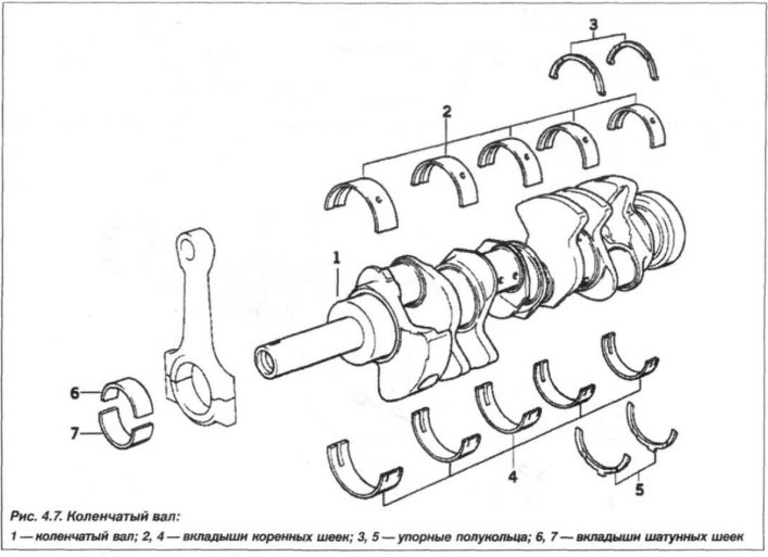
The engine crankshaft is a four-bearing, cast iron with spheroidal graphite. The bearings are made in the body of the cylinder block crankcase in the form of plain bearings. Lubricating grooves are made in the upper liners of the main bearings. Counterweights are made on the cheeks of the shaft, cast together with the shafts. The crankshafts are divided into three dimensional groups, marked with colored paint marks (yellow, green and white) on the cheeks in the area of the molar necks.
Diameter of crankshaft main journals:
yellow mark:
- nominal size - 69.984 - 69.990 mm:
- size 1st class - 69.734 - 69.740 mm;
(reduction by 0.25 mm)
- size 2nd class - 69.484 - 69.490 mm;
(decrease by 0.50 mm)
- size of class 3 - 69.234 - 69.240 mm.
(reduction by 0.75 mm)
green mark:
- nominal size - 69.977 - 69.983 mm;
- size 1st class - 69.727 - 69.733 mm;
(reduction by 0.25 mm)
- size 2nd class - 69.477 - 69.483 mm.
(decrease by 0.50 mm)
- size of class 3 - 69.227 - 69.233 mm.
(reduction by 0.75 mm)
white mark:
- nominal size - 69.971 - 69.976 mm;
- size 1st class - 69.721 - 69.726 mm;
(reduction by 0.25 mm)
- size 2nd class - 69.471 - 69.476 mm.
(decrease by 0.50 mm)
- size 3rd class - 69.221 - 69.226 mm.
(reduction by 0.75 mm)
Crankshaft axial clearance:
- nominal - 0.085 mm;
- maximum - 0.257 mm.
Radial clearance of crankshaft main bearings:
- nominal - 0.020 mm;
- maximum - 0.050 mm.
Diameter of crankshaft connecting rod journals:
- nominal size - 48.00 mm;
- 1st repair size - 47.75 mm;
- 2nd repair size - 47.50 mm;
- 3rd repair size - 47.25 mm.
with a performance tolerance from -0.009 to -0.025 mm.
Radial clearance of connecting rod bearings:
- nominal - 0.016 mm;
- maximum - 0.055 mm.
The maximum permissible ovality of the surfaces of the main and connecting rod journals is no more than 0.003 mm.
Crankshaft bearing shells
The main and connecting rod bearing shells are bimetallic three-layer.
Radial clearance between bearing shells and crankshaft main/connecting rod journals:
- nominal - 0.016/0.016 mm;
- maximum permissible - 0.055/0.055 mm.
The permissible runout of the crankshaft, measured at the middle journal, is no more than 0.15 mm.
Thrust bearing width:
- nominal - 32.0 mm;
- 1st repair size - 32.2 mm;
- 2nd repair size - 32.4 mm;
- 3rd repair size - 32.6 mm;
execution tolerance from +0.050 to +0.020 mm.
If the gaps are greater than the maximum allowable, this indicates the need to replace the liners (half rings) on the crankshaft journals with new ones. If the crankshaft journals are worn, they are ground to the nearest repair size, and the liners are replaced with repair ones (increased thickness).
Flywheel and drive disk
The design of the flywheel and drive disk is identical to the M54 engine, see Fig. 3.11.
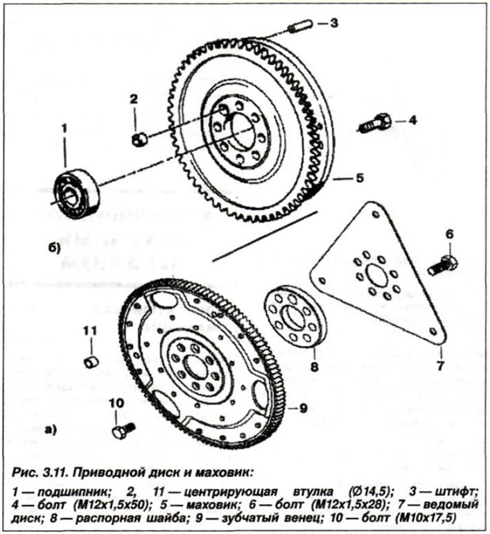
The M62 engine comes standard with an automatic transmission with a drive disk. A manual transmission with a dual-mass flywheel can be installed as an option.
The drive disk (with automatic transmission) or dual-mass flywheel (with manual transmission) are attached to the crankshaft flange with eight bolts. After removing the bolts, replace them with new ones, having first applied a locking compound to their threaded part.
The bolts for fastening the drive disk (flywheel) of the engine model "M62" should be tightened crosswise:
- dual-mass flywheel with a torque of 10.5 kgf·m (105 N·m).
- drive disk with a torque of 12.0 kgf·m (120 N·m).
The permissible runout of the drive disk (flywheel) for all engine models, when measured along the outer circumference, is no more than 0.20 mm.
Torsional vibration damper
The design of the torsional vibration damper is shown in Fig. 4.8.
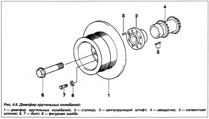
The torsional vibration damper has a diameter of:
- engine model "M62B44" - 270 mm;
- engine model "M62B46" - 275 mm.
Marking color, black. Permissible axial runout, no more than 0.30 mm. Permissible ovality, no more than 0.20 mm.
Pistons
The design of the pistons and connecting rods of the cylinder block is shown in Fig. 4.9.
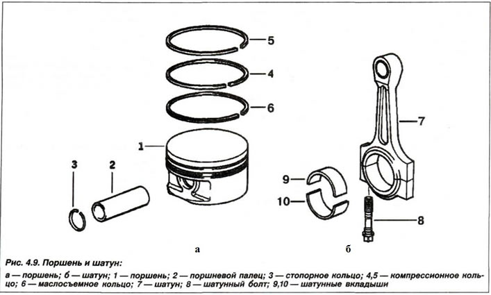
The pistons are made of aluminum alloy with steel inserts by Mahle (Germany). Each piston has two compression rings and one oil scraper ring. For correct orientation of the piston when installed in the cylinder, there is an arrow on its bottom, which should face the camshaft drive, as well as a mark indicating its diameter. The piston diameter is measured at a distance "A" from the lower edge of the piston skirt at an angle of 90° relative to the axis of the piston pin.
The repair size of pistons is only permissible for a cast aluminum cylinder block with thin-walled gray cast iron liners.
Engine model "M62B44":
Piston diameter:
- nominal - 91.990 mm;
- intermediate - 92.070 mm;
- 1st repair (+0.25) - 92.240 mm;
- 2nd repair (+0.50) - 92.490 mm.
Calculated clearance between piston and cylinder:
- for new parts - from 0.006 to +0.038 mm;
- maximum allowable - 0.10 mm;
Engine model "M62B46":
Piston diameter:
- nominal - 92.980 mm;
- intermediate - 92.994 mm;
Calculated clearance between piston and cylinder:
- for new parts - from 0.006 to +0.034 mm;
- maximum allowable - 0.10 mm;
The permissible difference in weight between pistons for one engine is no more than 10 g.
The maximum permissible deviation of the piston diameter from the nominal size must not exceed 0.014 mm.
The piston diameter is measured at a distance "A" from the lower edge of the piston skirt, equal to:
- engine model "M62B44" - 12 mm;
- engine model "M62B46" - 21.5 mm.
Piston pins
The piston pin is steel, ground, floating type. It is held from axial movement by two retaining rings in the piston holes for the piston pin. The pins are made in two classes, marked with color marks - black and white.
Piston pin length: 62 mm.
The piston pin diameter for all engine models is 22 mm, with a manufacturing tolerance of -0.003 to -0.006 mm.
Nominal clearance between piston pin and piston — 0.00092 – 0.006 mm;
Clearance between piston pin and connecting rod upper head bushing:
- fingers with a "white" mark - 0.003 - 0.005 mm.
- fingers with a "black" mark - 0.005 - 0.007 mm.
The permissible operating clearance between the piston pin and the connecting rod upper head bushing is 0.0092 mm.
When repairing an engine, only pistons and pins of the same configuration should be installed.
Piston rings
The piston rings are installed in the grooves of the piston head: two compression rings and one oil scraper ring.
The rings are installed on the piston with the mark "Top" ("Top") towards the bottom of the piston (fire belt).
The upper compression ring is chrome-plated, with rounded edges, the lower compression ring is conical, the oil scraper ring has an expander.
Clearance between new piston ring and groove wall:
Engine model "M62B44":
- upper compression - 0.002 - 0.060 mm;
- lower compression - 0.002 - 0.060 mm;
- oil scraper - not measured;
- the maximum permissible size is 0.12 mm.
Engine model "M62B46":
- upper compression - 0.002 - 0.070 mm;
- lower compression - 0.002 - 0.060 mm;
- oil scraper - 0.020 - 0.060 mm;
- the maximum permissible size is 0.12 mm.
Clearance in the lock of the new piston ring:
Engine model "M62B44":
- upper compression - 0.10 - 0.30 mm;
- lower compression - 0.20 - 0.40 mm;
- oil scraper - 0.20 - 0.90 mm;
Engine model "M62B46":
- upper compression - 0.10 - 0.30 mm;
- lower compression - 0.20 - 0.40 mm;
- oil scraper - 0.25 - 0.50 mm;
The maximum permissible gap in the lock for all engine models is 0.80 mm for compression rings and 1.00 mm for oil scraper rings.
Connecting rods
The design of the connecting rods is shown in Fig. 4.9.
The connecting rods are forged, with an I-section rod made of heat-treated steel, with thin-walled trimetallic plain bearing liners. A bimetallic, collapsible bearing is pressed into the upper head of the connecting rod (rolled up) bushing. According to the diameter of the hole of the lower head, the connecting rods are divided into two size groups, marked with color marks of red and blue.
Connecting rod lower head bore diameter:
- with red mark - 52.000 - 52.006 mm;
- with blue mark - 52.007 – 52.013 mm.
The lower connecting rod head undergoes final processing with its cover and is not subject to further disassembly.
Connecting rod upper head bushing diameter:
- outer — 24.060 – 24.100 mm;
- internal - 22.005 - 22.012 mm.
The maximum permissible operating clearance between the connecting rod bearings and the crankshaft journals for all engine models is 0.12 mm.
The permissible difference in weight between connecting rods on one engine is no more than 3.0 g.
The permissible twisting of the connecting rod for all engine models is no more than 30'.
The tolerance for non-parallelism and skew of the axes of the holes over a length of 100 mm, for all engine models, is no more than 0.04 mm.
The maximum permissible axial clearance of the connecting rod on the crankshaft journal relative to its cheek for all engine models is 0.37 mm.
This article is available at russian, bulgarian, belarusian, ukrainian, serbian, croatian, romanian, polish, slovak, hungarian
Article verified: Zhuravleva Isolda
Share information:
Previous articles
БМВ E53: Engine repair
Next articles
Similar articles on other types of BMW cars:
Characteristics of the crank mechanism BMW 3 Series E21 (1975-1983)
Gear shift mechanism BMW 3 Series E30 (1982-1994)
Crank mechanism parts BMW 5 Series E12 (1972-1981)
General description of the car BMW 7 Series E32 (1986-1994)
Fuses — general description BMW X3 E83 (2003-2010)
Characteristics of the crank mechanism BMW 3 Series E21 (1975-1983)
Gear shift mechanism BMW 3 Series E30 (1982-1994)
Crank mechanism parts BMW 5 Series E12 (1972-1981)
General description of the car BMW 7 Series E32 (1986-1994)
Fuses — general description BMW X3 E83 (2003-2010)
Link in different formats to this page
Visitor comments
No comments yet
- General information
- Manual
- Maintenance
- M54 petrol engine
- Engine repair
- Lubrication system
- Cooling system
- Supply system
- Injection system
- Exhaust system
- Engine electrics
- M62 petrol engine
- Engine repair
- Lubrication system
- Cooling system
- Supply system
- Exhaust system
- Engine electrics
- N62 petrol engine
- Engine repair
- Cooling and lubrication system
- Power and exhaust system
- Engine electrics
- Diesel engine M57
- Engine repair
- Lubrication system
- Cooling system
- Power and exhaust system
- Engine electrics
- Turbocharging system
- Transmission
- Clutch
- Mechanical gearbox
- Automatic gearbox
- Transfer case and cardan
- Chassis
- Brake system
- Steering
- Front suspension
- Rear suspension
- Wheels and tires
- Body
- Exterior
- Interior
- Doors and windows
- Repair and maintenance
- Heater and air conditioner
- Electrical equipment
- Equipment and devices
- Levers and switches
- Electrical circuits