
The replacement of the seals of both cylinder head covers of the engine must be carried out in the following order.
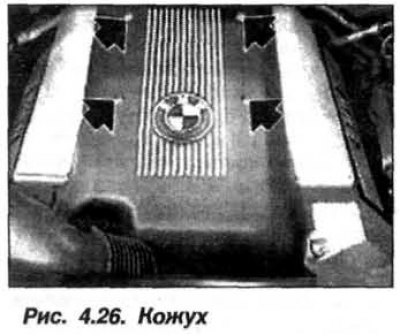
Disconnect the negative terminal from the battery and remove the soundproofing casing (see fig. 4.26) and a partition.
Remove the corrugated cover from the throttle shaft and the upper part of the air filter housing together with the air flow meter. Remove the lower part of the air filter housing and unscrew the "+" wire of the battery on the front shield of the engine compartment. Insulate the wire with a cap with insulating tape. Remove the "+" wire of the battery and move it to the side.
Remove the washer fluid reservoir from the cylinder head cover side of 1-4 cylinders. Release the cooling system hoses from the clamps and from the bracket on the valve and move them to the side from the cylinder head cover side of 5-8 cylinders. Do not disconnect the hoses.
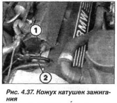
The ventilation duct is located under the ignition coil housing (1, Fig. 4.37) front axle gearbox and "+" wire (2) battery.
Open the ignition coil housing plugs and remove the ignition coils.
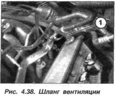
On cylinder bank 5 – 8, disconnect the hose (1, Fig. 4.38) crankcase ventilation from the cylinder head cover.
Loosen the mounting bolts and move the right and left cable boxes to the center of the engine.
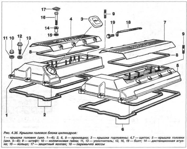
Unscrew the left and right fastening elements (11 pcs.) of the cylinder head cover and remove the cover.
The installation of the covers should be carried out in the reverse order, while it is necessary to check the condition of the sealing gaskets and, if necessary, replace them.
Clean the sealing surfaces of the cylinder head and head cover from the remains of the old seal. Use a hardwood scraper for cleaning (beech, hornbeam, oak).
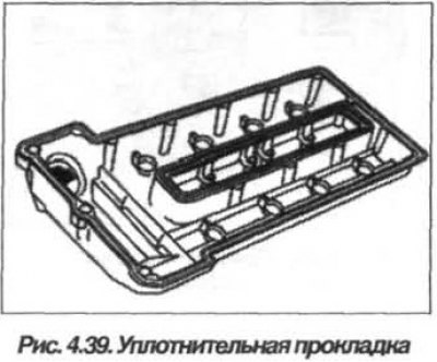
Apply a lubricant to improve rubber sliding, such as glycerin or petroleum jelly, around the entire perimeter of the outer and inner grooves, as well as to the sealing surface of the cylinder head cover (Fig. 4.39).
Install the inner gasket into the groove without tension, starting from the rounded corners. Install the outer gasket into the groove without tension and align it with the groove in the cover, starting from the rounded corners.
At the joints between the cylinder head and the timing belt cover on the left and right sides (arrows, Fig. 4.40, a)
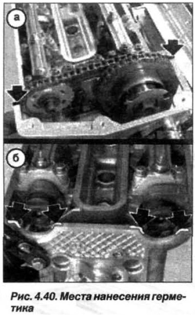
and in the rounding areas between the cylinder head and the VANOS actuators on the left and right sides (arrows, Fig. 4.40, b) apply bead sealant such as Drei Bond 1209. Ensure that the sealing gasket is correctly installed at the edges and at the rear of the cylinder head.
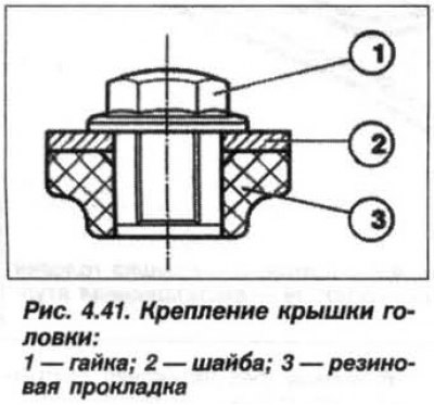
Prepare the cylinder head cover mounting bolts. The sequence of installing the bolt elements is shown in Figure 4.41.
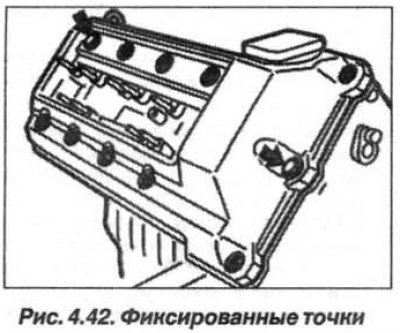
Insert cover mounting bolts into fixed points (arrows, Fig. 4.42) and align the cylinder head cover.
Screw in all the bolts (M6) securing the cover by hand, without tightening them completely.
Tighten the cover mounting bolts in a crisscross pattern from the middle to the edges. Do not overtighten the bolts.