
Table of contents: Replacing the left cylinder head ↓ Replacing the right cylinder head ↓
- Home
- BMW X5
- E53
- M62 petrol engine
- Engine repair
- Replacing cylinder heads
Replacing cylinder heads (BMW X5 E53)
Replacing the left cylinder head
The left cylinder head includes cylinders 5–8. Removal of the left cylinder head must be carried out in the following order.
Remove the left exhaust manifold, drain and dispose of the coolant.
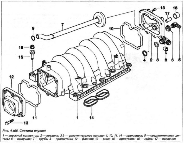
Remove the covers of both cylinder heads, unscrew the spark plugs. Remove the intake manifold (see fig. 4.108)
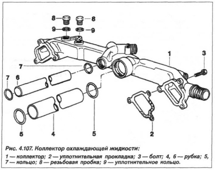
and coolant manifold (see fig. 4.107).
Remove the VANOS actuator from the left cylinder head. Remove the locking pin "11.5.180" enough to release the crankshaft flywheel (Fig. 4.43).

Pull the camshaft drive chain and hold it taut.
Turn the crankshaft by the central bolt against the direction of rotation to a position 45° before the top dead center (TDC) at the end of the compression stroke (Fig. 4.44)
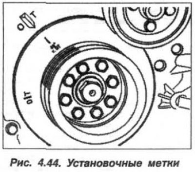
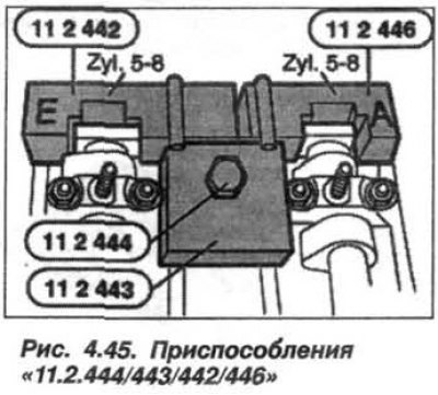
and remove the devices "11.2.444/443/ 442/446" (Fig. 4.45).

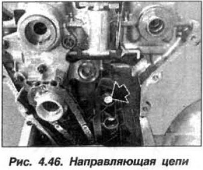
Loosen the bolt (arrow, Fig. 4.46) cylinder heads.

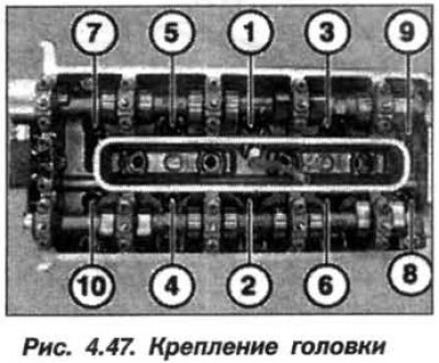
Loosen and unscrew the cylinder head mounting bolts in sequence 10 – 1 (Fig. 4.47).
Remove the cylinder head and sealing gasket; the gasket cannot be used further.
The installation of the cylinder head must be carried out in the reverse order, while it is necessary to clean the seals (docking) surfaces on the timing belt cover, cylinder head and engine block, using only a hardwood scraper for this purpose (oak, hornbeam, beech). Make sure that no sealant residue gets into the air, oil and coolant supply channels.
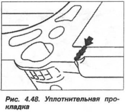
Apply a sealing compound such as Drei Bond 1209 to the junction of the cylinder head and timing cover (arrow, Fig. 4.48).
Check the centering bushings for damage and correct installation. Replace the cylinder head gasket by installing it on the centering bushings.
Attention! For the cylinder block head with treated sealing surface, install a thicker (0.3 mm) sealing gasket.
Do not wash off the coating on the new cylinder head bolts. Insert the bolts and tighten them by hand, crosswise, starting from the middle and moving towards the edges of the cylinder head. Using a pressure wrench and the "00.9.120" device, tighten the bolts (M10) in the sequence 1 - 10 (see fig. 4.47) in three consecutive doses:
- 1st step, torque 30 Nm (3.0 kgf·m);
- 2nd step, turn at an angle of 80°:
- 3rd step, turn to an angle of 80°.
Install the chain guide bolt (see fig. 4.46) and tighten it.
Attention! When adjusting the camshafts, avoid damaging them and use a modified key.
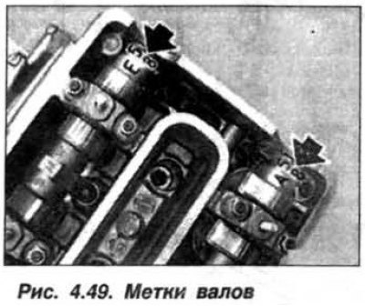
Turn the camshafts until the shaft timing marks (A5–8, E5–8, arrows, Fig. 4.49) are facing upward.

Install the fixtures "11.2.446/442" (see fig. 4.45) on the camshafts on cylinder bank 5–8.
Using a modified wrench (Fig. 4.50),
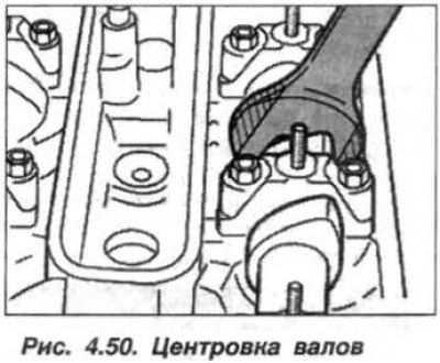
center the camshafts so that the fixtures "11.2.446/442" fit snugly against the cylinder head without gaps. Install the "11.2.443" device onto the device "11.2.446/442" and secure it with bolts "11.2.444" screwed into the spark plug socket.
Pull the drive chain up and hold it taut. Turn the crankshaft from the 45° BTDC position in the direction of rotation to the TDC position at the end of the compression stroke. Lock the crankshaft at TDC using the locking device "11.5.180" (see fig. 4.43).
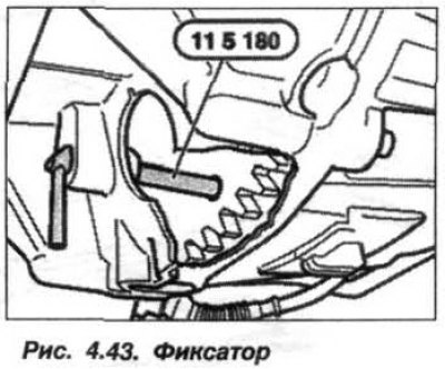
Attention! After completing the engine assembly, do not forget to remove the retainer.
Install the VANOS unit of the left cylinder block. Assemble the engine, replacing the gasket of the bolt (M14x1.5) of the drain hole of the engine cylinder block and tightening it to a torque of 25 N·m (2.5 kgf·m). Bleed the cooling system and check it for leaks.
Replacing the right cylinder head
The right cylinder head includes cylinders 1–4 and its removal must be carried out in a similar technological sequence, taking into account that before removing the intake manifold, the cooling system fan and its drive clutch must be removed.
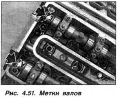
Turn the camshafts until the shaft timing marks (A1–4, E1–4, arrows, Fig. 4.51) are facing upwards, similar to Fig. 4.49.
 |
 |
This article is available at russian, bulgarian, belarusian, ukrainian, serbian, croatian, romanian, polish, slovak, hungarian
Article verified: Zhuravleva Isolda
Share information:
Previous articles
БМВ E53: Engine repair
Next articles
Similar articles on other types of BMW cars:
Removal and installation the cylinder head / replacing the sealing… BMW 3 Series E46 (1998-2006)
Checking the level and replacing the oil in the automatic transmission BMW 3 Series E21 (1975-1983)
Replacing the camshaft drive belt of the 6-cylinder BMW «520» and… BMW 5 Series E12 (1972-1981)
Removal and installation the cylinder head / replacing the cylinder… BMW 5 Series E39 (1995-2003)
Removal and installation of cylinder heads, camshafts and their… BMW 7 Series E38 (1994-2001)
Replacing the oil filter (center bolt design) BMW 7 Series E32 (1986-1994)
Cylinder head BMW X3 E83 (2003-2010)
Link in different formats to this page
Visitor comments
No comments yet
- General information
- Manual
- Maintenance
- M54 petrol engine
- Engine repair
- Lubrication system
- Cooling system
- Supply system
- Injection system
- Exhaust system
- Engine electrics
- M62 petrol engine
- Engine repair
- Lubrication system
- Cooling system
- Supply system
- Exhaust system
- Engine electrics
- N62 petrol engine
- Engine repair
- Cooling and lubrication system
- Power and exhaust system
- Engine electrics
- Diesel engine M57
- Engine repair
- Lubrication system
- Cooling system
- Power and exhaust system
- Engine electrics
- Turbocharging system
- Transmission
- Clutch
- Mechanical gearbox
- Automatic gearbox
- Transfer case and cardan
- Chassis
- Brake system
- Steering
- Front suspension
- Rear suspension
- Wheels and tires
- Body
- Exterior
- Interior
- Doors and windows
- Repair and maintenance
- Heater and air conditioner
- Electrical equipment
- Equipment and devices
- Levers and switches
- Electrical circuits