
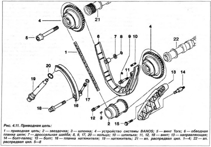
Engine drive chains are designed to transmit rotation:
- camshafts (21, 22, see Fig. 4.11) intake valves of both cylinder heads from the crankshaft (main chain, 1);
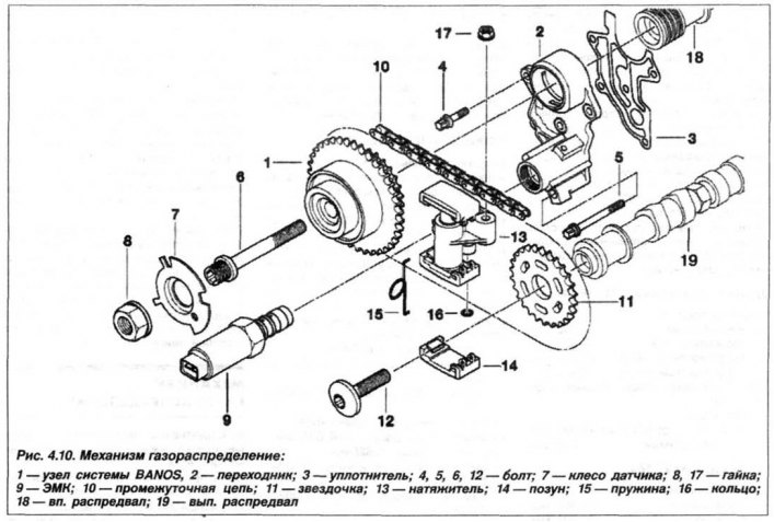
- from the camshaft of the exhaust valves to the camshaft of the intake valves (intermediate chain, 10, see Fig. 4.10);
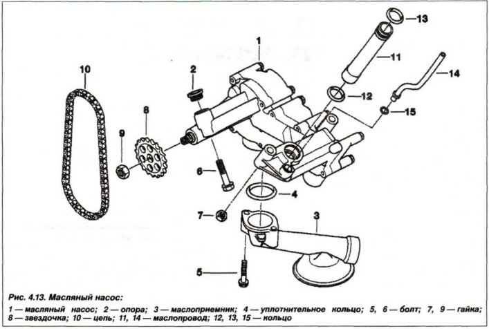
- oil pump (see fig. 4.13) from the engine crankshaft.
The engine uses a valve timing mechanism with overhead intake and exhaust camshafts, the cams of which act on the valves through hydraulic tappets.
The intake camshaft is driven by a roller chain from the crankshaft sprocket, and the exhaust camshaft is driven by the intake shaft sprocket, thanks to an intermediate chain. The intake camshaft has a mechanism for changing the angle of the initial position (rotation), the VANOS system, which changes the opening phase of the intake valves.
The valve timing mechanism includes the cylinder head, camshafts, intake and exhaust valves, valve guides, valve springs with fastening parts, hydraulic tappets, camshaft drive chains with tension parts.
The chain tension is adjusted by an automatic tensioner with a hydraulic damping mechanism. The camshaft and crankshaft sprockets are mounted on segment keys and secured with bolts.
Camshaft
The design of the camshafts is shown in Fig. 4.12.
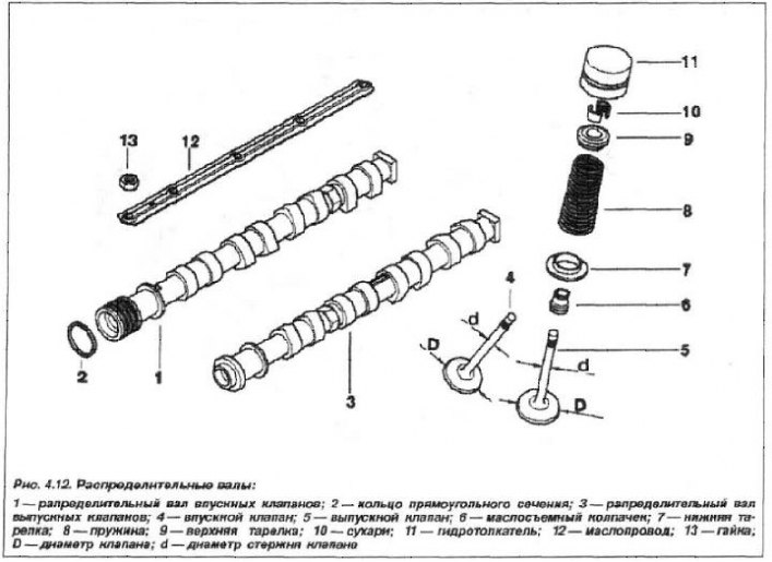
The camshaft has five bearings and rotates in plain bearings. Two drive chain sprockets are installed on the intake camshaft.
Axial displacement of the camshaft:
- nominal - 0.20 - 0.36 mm;
- maximum permissible - 0.45 mm.
Radial runout of the shaft journals for engine models during assembly, no more than 0.040 – 0.074 mm. Limit value in operation is 0.1 mm.
Thrust bearing width: 22.1 – 22.2 mm.
The gap between the shaft journals and their bearings is 0.040 – 0.074 mm.
Camshaft lobe height:
- inlet - 47.7±0.05 mm;
- outlet - 47.3±0.05 mm.
Valve lift:
- inlet - 9.7 mm;
- outlet - 9.4 mm.