
The engine crankshaft must be replaced in the following order: Remove the engine, oil pan, oil pump and lower timing belt cover.
Remove all pistons, drive disc and rear crankshaft oil seal cover. Check crankshaft end clearance (see fig. 3.87).
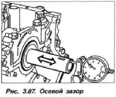
If the permissible axial clearance (0.085–0.257 mm) is exceeded, replace the half rings of the crankshaft thrust bearing shells.
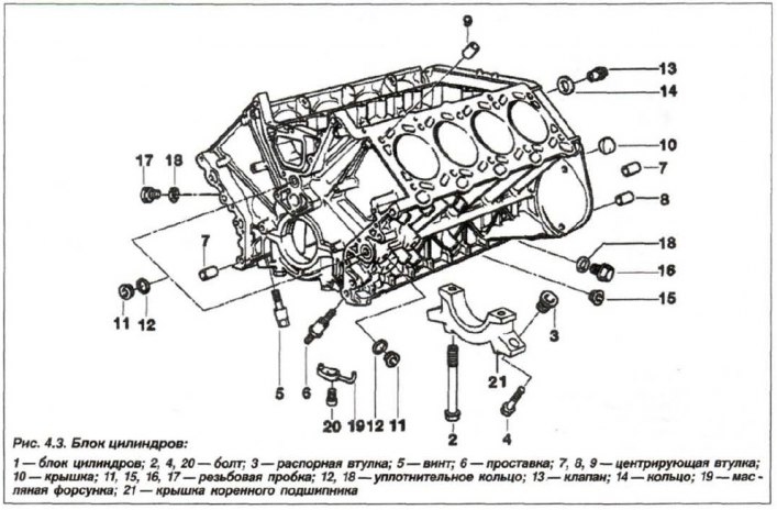
Sequentially loosen all the outer bolts in the threaded bushings of the main bearing cap bosses and unscrew them (10 pcs.). Sequentially loosen all the main bearing cap fastening bolts and unscrew them (10 pcs., Fig. 4.81).
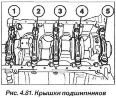
Check the marking (numbering in circles, 1–3), if not, apply it, and remove the main bearing caps 1–5. The main bearing caps 4 and 5 have no marking. The bearing cap No.5 is a thrust cap. Remove the crankshaft and pay attention to its marking (see fig. 3.73).
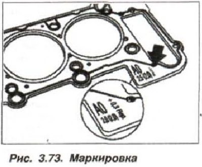
Note: The crankshaft is marked yellow, green or white according to the main journal diameter.
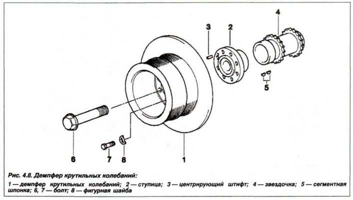
If necessary, remove the sprocket from the crankshaft; to do this, use the device "11.2.383" (Fig. 4.82) installed on the crankshaft.

The sprocket is removed using the device "11.2.001", equipped with the devices "11.2.005" and "11.2.004".
The installation of the sprocket must be carried out in a state heated to 150°C. Heating should be carried out with an industrial hair dryer or a heating plate. Exceeding the temperature is unacceptable.
Check the correct fit of the keys (5, see Fig. 4.8).
Replace the main and connecting rod bearing shells of the crankshaft, checking their radial clearance.
The technology for replacing main and connecting rod bearing liners is similar to the M54 engine model.
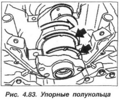
Attention! Carefully ensure that the grooves of the thrust half rings are facing the crankshaft cheeks.
The color marking of the liners in the main bearing cap must match the marking on the crankshaft.
Install the thrust bearing half rings so that the grooves (arrows, Fig. 4.83) the oil supply ports were facing towards the crankshaft cheeks.
Screw the threaded bushings with internal hexagon into the lugs of the main bearing cap.
Note: The main bearing caps (1–3) are marked with stamped numbers. The caps of bearings 4 and 5 are not marked.
Using a pressure wrench and the "00.9.120" tool, tighten all the bolts securing all the main bearing caps in two steps:
- the first time - with a torque of 20 Nm (2.0 kgf·m);
- the second time (M10) – turn to an angle of 70°;
- the second time (M11) – turn to an angle of 100°.
The radial clearance of the crankshaft main bearings should be within 0.020 - 0.050 mm. To adjust the clearance in the bearing, use new liners with a different color marking.
Use new main bearing cap bolts, do not wash off their coating. Install and hand tighten the main bearing cap bolts.
Install new main bearing cap mounting bolts and tighten to a torque of 20 N·m (2.0 kgf·m).
Loosen the fasteners of the thrust main bearing cap (No. 5). Tap the end of the crankshaft from the back and front with a mallet or plastic hammer to center the thrust bearing.
Tighten the main bearing cap mounting bolts (No. 5) to a torque of 20 N·m (2.0 kgf·m).
Using the "00.9.120" device, tighten all the main bearing cap mounting bolts to the specified angle: M10 bolts – 70°, M11 bolts – 100°.
Check the value of the crankshaft axial clearance (Fig. 3.87), which should be within 0.085–0.257 mm.

If the permissible axial clearance is exceeded, check and, if necessary, replace in the following order - liner (half rings) thrust bearing, crankshaft and engine block.
Tighten the threaded bushings to a torque of 10 N·m (1.0 kgf·m), and the new main bearing cap tailstock mounting bolts to a torque of 20 N·m (2.0 kgf·m).
Tighten all main bearing cap mounting bolts to a specified angle of 70° for M10 bolts or to an angle of 100° for M11 bolts.
(The original text can be read on the website: «www.bmwman.ru»)