
Note: There is very little space to remove the engine oil pan, so it is necessary to lower the front axle beam.
Do not measure the front wheel alignment angles after completing the work.
Removal of the upper part of the oil pan must be carried out in the following order, prepare the tools "11.0.000", "00.0.200", "00.0.208", "00.0.201", "00.0.202", "00.0.204", "00.2.030". "31.2.220" and "51.2.170", disconnect the "–" terminal from the battery and remove the heater partition in the engine compartment.
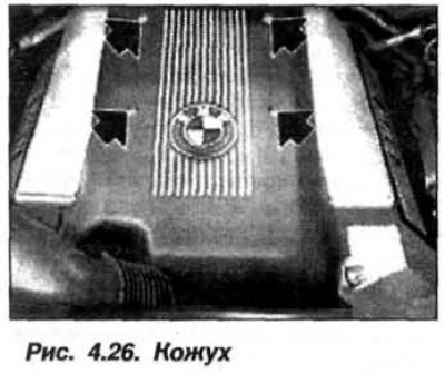
Fix the hood in the installation position using the device "51.2.170" and remove the soundproofing casing (see fig. 4.26).
Remove the corrugated boot from the throttle shaft and the upper part of the air filter housing together with the air flow meter.
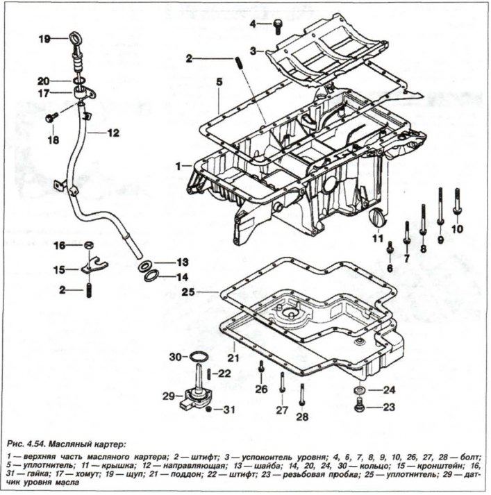
Disconnect the guide tube (12, see Fig. 4.54) oil dipstick (19) from the right timing belt cover.
Assemble the "00.0.200" fixture together with the fixtures "00.0.201/202/204/208" and install them (Fig. 4.55) on the engine compartment of the car.
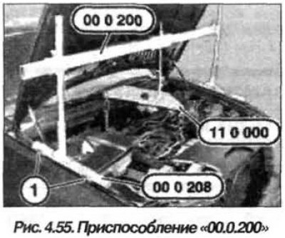
The supports (1) of the "00.0.208" tool must rest on the bolts in both body wings. Install the "11.0.000" tool on the "00.0.200" tool as shown in Figure 4.55. Only in this case, after separating the front axle beam, the engine will hang horizontally. Secure the "11.0.000" tool to the front and rear engine lifting eyes.
Caution: Make sure that neither pipes nor wires will be damaged by the chain.
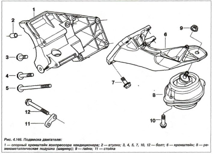
Unscrew the top nuts (9, see Fig. 4.146) on the left and right engine mounts and raise the engine using the "00.0.200" tool by approximately 10–12 mm.
Remove the front engine sump guard panel and the stiffening plate. Unscrew the "+" cable fastening from the starter and release it from the clamps.
Remove the left and right swivel bearings, front wheel drive shafts, right output shaft support bracket from the oil pan and the front propeller shaft.
Disconnect the steering shaft from the steering gear and again, temporarily install the left and right pivot bearings and connect them with one bolt to the shock absorber strut. Temporarily connect the tie rod, the transverse suspension arm and the transverse steering rod to the pivot bearing. Remove the front axle gearbox.
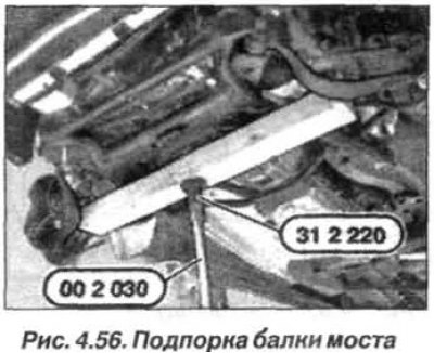
Using the devices "00.2.030" and "31.2.220", together with a wooden block (1), support the front axle beam as shown in Fig. 4.56.
Disconnect the front axle beam from the front side member and carefully lower it by 90–100 mm.
Caution! The steering gear remains attached to the front axle beam. When lowering the front axle beam, make sure that the steering gear hoses are not stretched.
Remove the alternator drive belt and remove the power steering pump from the oil pan. Leave the pipes connected. Move the pump to the side and secure it to the body with a wire clip. Loosen the air conditioning compressor drive belt and remove the tensioner bar from the oil pan.
Unscrew the oil drain plug and drain the oil from the engine. Dispose of the oil. Mark the bolts securing the lower part of the oil pan, as they are of different lengths on the timing belt and gearbox sides. Unscrew the bolts securing the oil pan and remove the lower part of the oil pan.
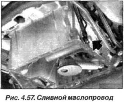
Disconnect the dipstick guide tube from the oil pan and the oil drain line (arrow, Fig. 4.57), which goes from the oil separator of the engine crankcase ventilation system to the oil pan.
Disconnect the oil drain line that goes from the oil filter to the oil pan and remove the oil pump intake.
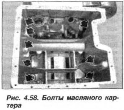
Remove the bolts (arrows, Fig. 4.58) inside the oil pan.
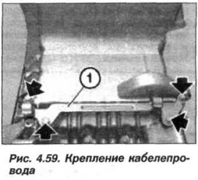
Unscrew the bolts (arrows) and remove the cable duct (1, Fig. 4.59) "+" wires of battery.
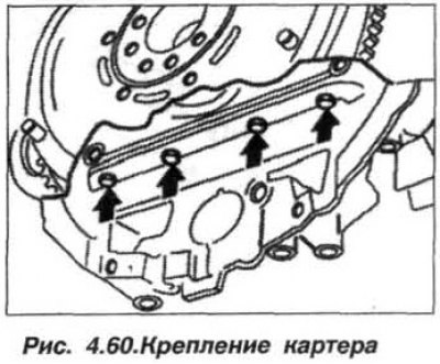
Remove the bolts (arrows, Fig. 4.60) oil pan mounts on the gearbox side.
Remove the remaining bolts securing the upper part of the oil pan and remove the upper part of the oil pan in a rearward direction.
The installation of the oil pan should be carried out in the reverse order, using a scraper made of hardwood (beech, hornbeam or oak), clean the sealing surfaces from the remains of the old gasket.
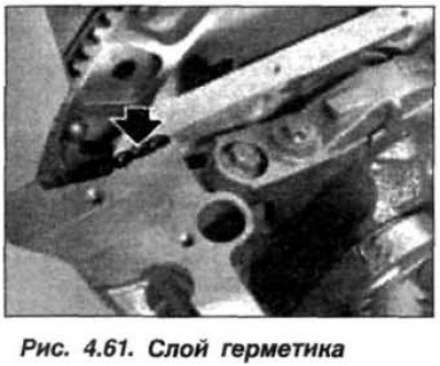
In the area of the joints of the rear crankshaft oil seal cover and the block, apply a layer of sealant such as "Drei Bond 1209" approximately 3 mm wide and 2 mm high (Fig. 4.61).
Secure the new seal to the pan with a small amount of grease and check that it is positioned correctly.
Insert all the bolts securing the upper part of the oil pan and screw them in by hand, without tightening. Tighten the bolts on the timing belt and cylinder block side. Tighten the bolts on the automatic transmission side. Tighten the bolts to a torque of 10–12 N·m (1.0–1.2 kgf·m), do not overtighten, otherwise the gasket will become unsealed.
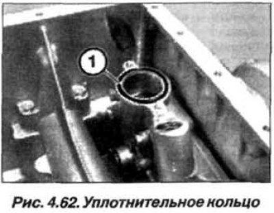
Replace the sealing ring round section (1, Fig. 4.62) oil intake.
Replace the sealing rings of the oil drain lines and tighten their hollow bolts M12x1.5 to a torque of 25 N·m (2.5 kgf·m), bolts M14x1.5 to a torque of 30 N·m (3.0 kgf·m).
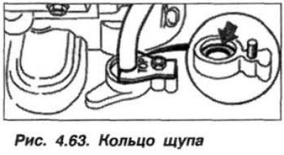
When installing the dipstick guide tube, insert a new ring (arrow, Fig. 4.63) round section and a washer into the hole in the oil pan.
Assemble the engine. Fill the engine with oil and check the oil level in the engine and the power steering reservoir.
Take a test drive and check the oil pan for leaks. If necessary, slightly tighten the engine crankcase mounting bolts.
Replacement of the oil pan (21, see Fig. 4.54) the engine crankcase must be repaired in the following order.
Unscrew the oil filter cap and allow the oil to drain into the engine sump.
Remove the stiffening plate, unscrew the oil drain plug and drain the oil from the engine. Disconnect the plug connector (SC) from the oil level sensor (29) and release the wiring harness from the clamps.
Remove the bolts (26, 27, 28) and remove the lower part (21) of the oil pan.
When installing the pan, clean the sealing surfaces and replace the sealing gasket (25). Insert all bolts (M8) and tighten them to a torque of 22 N·m (2.2 kgf·m), tighten the bolts (M6) to a torque of 10–12 N·m (1.0–1.2 kgf·m).
(The article text was copied from an online resource: BMWman.ru)