
Prepare tools "00.2.590" and "00.9.120" and remove all pistons.
Note: Connecting rod head bearings are different from connecting rod cap bearings. Pay attention to the crankshaft size marking.
Install a new standard insert with a red marking into the connecting rod cap, and install an insert with a blue marking into the lower connecting rod head (regardless of the color marking of the connecting rod). Install the pistons into the cylinder block.
Check the radial clearance between the liners and the connecting rod journal, which should be within 0.016 - 0.055 mm. When checking the clearance, use the old connecting rod lower head cover fastening bolts.
Set the piston to the bottom dead center (BDC) position. The tightening sequence of the connecting rod bearing cap is as follows:
- tighten to 5.0 Nm (0.5 kgf·m);
- tighten to 20.0 N·m (2.0 kgf·m);
- tighten the bolts to an angle of 80°.
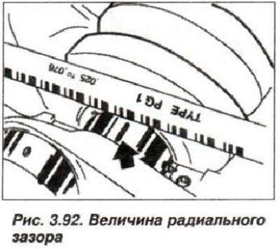
Remove the connecting rod bearing cap and measure the radial clearance using the width of a flattened plastic gauge wire (see fig. 3.92). To adjust the radial clearance, it is necessary to use new bearing shells or shells with different color markings.
Remove the calibration wire, lubricate the journals and liners with engine oil. Install the connecting rod caps with new, clean, engine oil-lubricated bolts. Tighten the connecting rod cap bolts in three stages:
- 1st reception with a torque of 5.0 N·m (0.5 kgf·m);
- 2nd reception with a torque of 20 N·m (2.0 kgf·m);
- 3rd step, turn it at an angle of 80°.