

Remove the engine accessory guard, both cylinder head covers and remove all spark plugs.
Remove the chain tensioner plunger. Note that the piston cylinder is under significant spring pressure. Remove the upper timing covers, left cylinder head VANOS adjustment unit and left cylinder head VANOS adjustment unit adapter.
Attention! If the camshafts are removed from the cylinder head mounted on the engine, then all pistons must be set to an intermediate position. This will eliminate the contact of valves and pistons, because. None of the pistons will be in the TDC position.
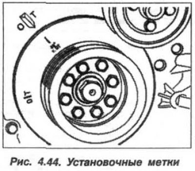
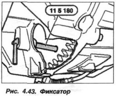
Pull back fixture «11.5.180» back enough to free the flywheel (see fig. 4.43). Pull the drive chain up and keep it taut. Turn the engine crankshaft at the central bolt against the direction of rotation to the position 45°to TDC, using the alignment marks (see fig. 4.44).
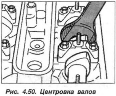
Attention! To expose and hold the camshafts, when removing and installing them, use only a modified wrench with cut jaws (see fig. 4.50), this will prevent damage to the cylinder head.
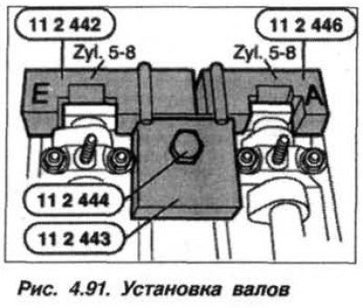
Remove fixtures «11.2.444», «11.2.443», «11.2.446» And «11.2.442» (see fig. 4.91).

When removing the tool «11.2.442» hold the inlet camshaft of cylinders 5-8 with a wrench.
Prepare the camshafts for removal, for which:
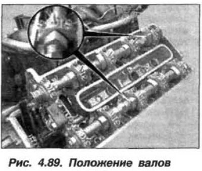
- turn the exhaust camshaft by the hexagon so that the cams of the valves of the 6th cylinder stand vertically upwards (the lower arrow of the circle, fig. 4.89):

- turn the intake camshaft by the hexagon so that the cams of the valves of the 8th cylinder stand vertically upwards (upper circle arrow).
Loosen the nuts (M7) fastening the bearing caps of the exhaust and intake camshafts on the bank of cylinders 5-8 in several half-turn steps, moving from the edges to the middle.
Attention! Bearing caps for camshafts 1-4 and 5-8 cylinders must not be interchanged.
Mark the positions of the covers in relation to the cylinders and camshafts. Remove bearing caps on cylinder bank 5-8 and fold them in order. When assembling, they must be installed in their places. Remove camshafts.
Installation of camshafts should be carried out in the following order.
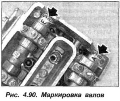
Install the exhaust and intake camshafts on cylinder bank 5-8. The exhaust camshafts are marked «A,5–8» (pic. 4.90), intake shaft - marking «E,5–8».

Turn the exhaust camshaft by the hexagon so that the cams of the valves of the 6th cylinder stand vertically upwards (bottom arrow, see fig. 4.89).
Turn the intake camshaft by the hexagon so that the cams of the valves of the 8th cylinder stand vertically upwards (top arrow).
Install bearing caps in place. The exhaust camshaft bearing caps are marked A1 to A5, readable from the intake side. The intake camshaft bearing caps are marked E1 to E5, readable from the intake side.
Tighten the nuts (M7) fastening the bearing caps of the exhaust and intake camshafts on the bank of cylinders 5-8 in several steps of half a turn, moving from the middle to the edges, with a final tightening torque of 14 Nm (1.4 kgf·m).
Align the camshafts with a modified wrench until the alignment marks of the shafts are facing up (arrows, fig. 4.90).
Install fixtures «11.2.446» (A) And «11.2.442» (E) (pic. 4.91) on the camshafts on the bank of cylinders 5-8.
Using the key (see fig. 4.50), adjust the position of the camshafts so that the tools «11.2.442» And «11.2.446» fit snugly to the cylinder head, without a gap.

Install fixture «11.2.443» (pic. 4.91) on fixtures «11.2.446» And «11.2.442» and fix it with a bolt «11.2.444», screwed into the spark plug hole.

Return the piston of the first cylinder to the TDC position of the compression stroke by rotating the crankshaft clockwise. Block the crankshaft in the TDC position of the end of the compression stroke using the tool «11.5.180» (see fig. 4.43).
Attention! Before starting the engine, remove the tool «11.5.180».
Install the left cylinder head VANOS adjustment adapter, VANOS adjustment unit, upper timing covers and chain tensioner plunger. Install the covers of both cylinder heads and assemble the engine.