
Table of contents: Checking the connecting rod bearing…↓ Final installation of the connecting…↓
- Home
- BMW 7 Series
- E32
- Power unit
- Engine overhaul
- Pistons and connecting rods — installation and checking of connecting rod bearing oil clearance
Pistons and connecting rods — installation and checking of connecting rod bearing oil clearance (BMW 7 Series E32)
Before installing the pistons and connecting rods, the cylinder walls must be thoroughly cleaned, the top edge of the cylinder chamfered, and the crankshaft installed in place.
Remove the cover from connecting rod #1 (they should have marks made during removal). Wipe the old bearing shells in the connecting rod and connecting rod cap with a clean, lint-free cloth.
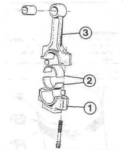
Connecting rod elements
1 - connecting rod cover;
2 — liners;
3 — connecting rod.
Clean the back of the new upper bearing shell, then slide it into place in the connecting rod. Make sure the key on the shell fits into the recess in the connecting rod. Do not hammer the shell or scratch the bearing surface. Do not lubricate the bearing yet. Clean the back of the second shell and install it in the connecting rod cap. Make sure the key on the shell fits into the recess in the cap, and do not apply grease yet.
Position the ring gaps around the piston circumference at an angle of 120°. The position of the ring gaps may differ from the required position by no more than 20°.
Place a piece of plastic or rubber tubing over each connecting rod cap bolt.
Lubricate the piston and rings with clean engine oil and attach a ring compressor to the piston. The skirt should extend about 6 mm to guide the piston into the cylinder. The rings should be compressed until they are flush with the piston.
Rotate the crankshaft until the No.1 crankpin is at the bottom dead center. Apply a layer of engine oil to the cylinder walls.
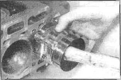
With the piston positioned so that the arrow or notch on the top of the piston points forward, carefully insert the piston into cylinder #1. The bottom of the ring compressor should rest on the cylinder block.
Make sure the ring compressors contact the cylinder block all the way around.
Gently press down on the top of the piston with the end of the wooden handle of the hammer, while simultaneously guiding the end of the connecting rod into place on the crankpin. The piston rings can pop out of the compression tool just before they enter the cylinder, so you need to press down on the tool from above. Work slowly and if you feel resistance as the piston enters the cylinder, stop immediately. Find out the cause and fix it. Never press down too hard on the piston - you can damage the rings and the piston itself.
After the piston and connecting rod are installed, it is necessary to check the size of the connecting rod bearing oil clearance before the connecting rod is finally screwed into place.
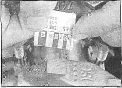
Cut a piece of plastic clearance filler of a suitable size, slightly shorter than the width of the connecting rod bearing, and place it on the #1 crankpin, parallel to its axis.
Clean the surface of the connecting rod bearing cap, remove the protective tubes from the connecting rod bolts and install the connecting rod cap.
Install the nuts and tighten them to the specified torque value in three stages. Do not rotate the crankshaft while doing this.
Unscrew the nuts and remove the connecting rod cover, being careful not to damage the plastic.
Compare the width of the crushed plastic to measure the gap with the scale on its package to determine the gap. Compare the obtained value with the technical data.
If the clearance is not within specification, the bearing shells may be the wrong size. But before you decide to replace the shells, check to see if any dirt or oil has gotten between the shells and the connecting rod or cap. Also, check the journal diameter. If the width of the plastic for measuring the clearances is different at each end of the strip, the journal may be tapered and need to be reground.
Carefully clean all traces of clearance measuring plastic from the journal and bearing surface, being careful not to scratch the bearing.
Make sure the bearing surfaces are completely clean and apply a uniform coat of grease to both bearings. You will have to push the piston into the cylinder to access the connecting rod bearing - remember to pull the protective tubes over the connecting rod bolts first.
Place the connecting rod on the shaft journal, remove the protective tubes from the connecting rod cap bolts, install the cap and tighten the nuts in three stages to the required tightening torque.
Repeat the above procedure for the remaining pistons and connecting rods.
Check the piston assembly.
Once all pistons and connecting rods are installed, turn the crankshaft by hand several times and check for binding.
Check the connecting rod play.
Compare the measured clearance with the technical data. If the clearance was within the norm before disassembly and the old connecting rods and crankshaft were used, it should remain within the norm. If new connecting rods or a new crankshaft were installed, the clearance may not correspond to the norm. In this case, it is necessary to remove the connecting rods and send them to a workshop for mechanical processing.
Remove the cover from connecting rod #1 (they should have marks made during removal). Wipe the old bearing shells in the connecting rod and connecting rod cap with a clean, lint-free cloth.
Connecting rod elements
1 - connecting rod cover;
2 — liners;
3 — connecting rod.
Checking the connecting rod bearing oil clearance
Clean the back of the new upper bearing shell, then slide it into place in the connecting rod. Make sure the key on the shell fits into the recess in the connecting rod. Do not hammer the shell or scratch the bearing surface. Do not lubricate the bearing yet. Clean the back of the second shell and install it in the connecting rod cap. Make sure the key on the shell fits into the recess in the cap, and do not apply grease yet.
Position the ring gaps around the piston circumference at an angle of 120°. The position of the ring gaps may differ from the required position by no more than 20°.
Place a piece of plastic or rubber tubing over each connecting rod cap bolt.
Lubricate the piston and rings with clean engine oil and attach a ring compressor to the piston. The skirt should extend about 6 mm to guide the piston into the cylinder. The rings should be compressed until they are flush with the piston.
Rotate the crankshaft until the No.1 crankpin is at the bottom dead center. Apply a layer of engine oil to the cylinder walls.
With the piston positioned so that the arrow or notch on the top of the piston points forward, carefully insert the piston into cylinder #1. The bottom of the ring compressor should rest on the cylinder block.
Make sure the ring compressors contact the cylinder block all the way around.
Gently press down on the top of the piston with the end of the wooden handle of the hammer, while simultaneously guiding the end of the connecting rod into place on the crankpin. The piston rings can pop out of the compression tool just before they enter the cylinder, so you need to press down on the tool from above. Work slowly and if you feel resistance as the piston enters the cylinder, stop immediately. Find out the cause and fix it. Never press down too hard on the piston - you can damage the rings and the piston itself.
After the piston and connecting rod are installed, it is necessary to check the size of the connecting rod bearing oil clearance before the connecting rod is finally screwed into place.
Cut a piece of plastic clearance filler of a suitable size, slightly shorter than the width of the connecting rod bearing, and place it on the #1 crankpin, parallel to its axis.
Clean the surface of the connecting rod bearing cap, remove the protective tubes from the connecting rod bolts and install the connecting rod cap.
Install the nuts and tighten them to the specified torque value in three stages. Do not rotate the crankshaft while doing this.
Unscrew the nuts and remove the connecting rod cover, being careful not to damage the plastic.
Compare the width of the crushed plastic to measure the gap with the scale on its package to determine the gap. Compare the obtained value with the technical data.
If the clearance is not within specification, the bearing shells may be the wrong size. But before you decide to replace the shells, check to see if any dirt or oil has gotten between the shells and the connecting rod or cap. Also, check the journal diameter. If the width of the plastic for measuring the clearances is different at each end of the strip, the journal may be tapered and need to be reground.
Final installation of the connecting rod
Carefully clean all traces of clearance measuring plastic from the journal and bearing surface, being careful not to scratch the bearing.
Make sure the bearing surfaces are completely clean and apply a uniform coat of grease to both bearings. You will have to push the piston into the cylinder to access the connecting rod bearing - remember to pull the protective tubes over the connecting rod bolts first.
Place the connecting rod on the shaft journal, remove the protective tubes from the connecting rod cap bolts, install the cap and tighten the nuts in three stages to the required tightening torque.
Repeat the above procedure for the remaining pistons and connecting rods.
Check the piston assembly.
Once all pistons and connecting rods are installed, turn the crankshaft by hand several times and check for binding.
Check the connecting rod play.
Compare the measured clearance with the technical data. If the clearance was within the norm before disassembly and the old connecting rods and crankshaft were used, it should remain within the norm. If new connecting rods or a new crankshaft were installed, the clearance may not correspond to the norm. In this case, it is necessary to remove the connecting rods and send them to a workshop for mechanical processing.
This article is available at russian, bulgarian, belarusian, ukrainian, serbian, croatian, romanian, polish, slovak, hungarian
Article verified: Sevastyanov Nikolay
Share information:
Previous articles
БМВ E32: Engine overhaul
Next articles
Similar articles on other types of BMW cars:
Pistons with connecting rods — installation BMW 3 Series E46 (1998-2006, petrol)
Checking the clearance between the bearings and the connecting rod… BMW 3 Series E21 (1975-1983)
Checking the condition of pistons / connecting rods BMW 5 Series E28 (1981-1988)
Checking the clearance between the bearings and the connecting rod… BMW 5 Series E12 (1972-1981)
Connecting electrical appliances BMW X3 E83 (2003-2010)
Pistons and connecting rods — design description BMW X5 E53 (1999-2006)
Link in different formats to this page
Visitor comments
No comments yet
- General information
- Introduction to guide
- Manual
- Maintenance
- Power unit
- Engine M60/1, M60/2 (petrol)
- M62 engine (petrol)
- M57 engine (diesel)
- M67 engine (diesel)
- Cooling system
- Fuel system (petrol)
- Fuel system (diesel)
- Exhaust system
- Ignition and control systems
- Charge and launch systems
- Transmission
- Clutch
- Mechanical gearbox
- Automatic gearbox
- Cardan and drive shafts
- Chassis
- Brake system
- Front suspension
- Rear suspension
- Steering
- Body
- Exterior
- Interior
- Electrical equipment
- Equipment and devices
- Lighting
- Heating and air conditioning
- Electrical circuits
- General information
- Care and maintenance
- Power unit
- Minor engine repair
- Engine overhaul
- Lubrication system
- Cooling system
- Ignition system
- Supply system
- Injection system (petrol)
- Injection system (diesel)
- Exhaust system
- Transmission
- Clutch
- Manual gearbox
- Automatic gearbox
- Cardan gear
- Rear axle and shafts
- Chassis
- Front suspension
- Rear suspension
- Steering
- Wheels and tires
- Brake system
- Body
- Body elements
- Electrical equipment
- Equipment and devices
- Electrical circuits