
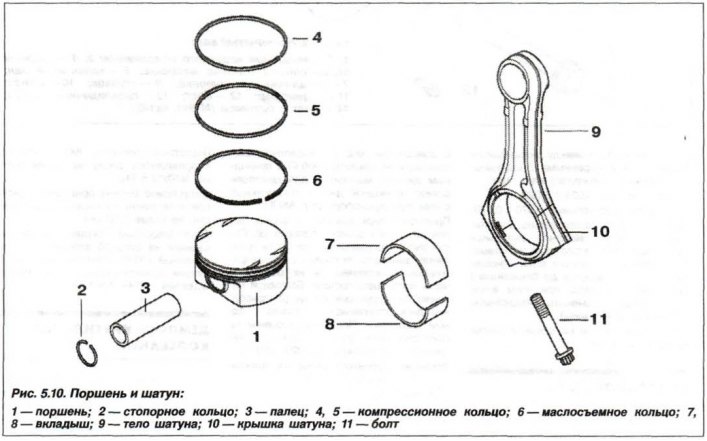
Pistons are made of aluminum alloy with steel inserts. Each piston has two compression rings and one oil scraper ring. For the correct orientation of the piston when installed in the cylinder, there is an arrow on its bottom, which must be turned towards the camshaft drive, as well as a mark indicating its diameter. The piston diameter is measured at a distance «A» = 18 mm from the lower edge of the piston skirt at an angle of 90°to the axis of the piston pin.
Model engine «N62B44»:
Piston diameter:
- nominal - 91.986±0.016 mm;
- size 1st class - 92.236±0.016 mm;
- size 2nd class - 92.486±0.016 mm.
Model engine «N62B48»:
Piston diameter:
- nominal - 92.985±0.016 mm;
- size 1st class - 93.235±0.016 mm;
- size 2nd class - 93.485±0.016 mm.
Estimated clearance between piston and cylinder:
- for new parts - from 0.001 to +0.044 mm;
- for working parts - from 0.026 to +0.073 mm;
- the maximum allowable is 0.10 mm.
Permissible difference in weight between pistons for one engine is no more than 10 g.
The maximum allowable deviation of the piston diameter from the nominal size should not exceed 0.016 mm.
piston pin (3) - steel, polished, floating type. From axial movement, it is held by two retaining rings (2) in the piston holes (1) under the piston pin (in bosses). Fingers are made in two classes and are marked with colored marks - black and white.
The piston pin diameter for all engine models is 21 mm, with a manufacturing tolerance of -0.003 to -0.006 mm.
The nominal clearance between the piston pin and the piston is from 0.00092 mm to 0.006 mm.
Clearance between piston pin and connecting rod bushing:
- fingers with «white» label - 0.003 - 0.005 mm.
- fingers with «black» label - 0.005 - 0.007 mm.
Permissible operating clearance between the piston pin and the bushing of the upper head of the connecting rod is 0.0092 mm.
When repairing the engine, only pistons and pins of the same configuration should be installed.
The piston rings are installed in the grooves of the piston head: two compression (4, 5) and one oil scraper (6). Rings are installed on the piston with a mark «Thor» («Top») to the bottom of the piston (fire belt).
Top compression ring (4) - chrome-plated, with rounded edges.
Lower compression ring (5) – cone, oil scraper ring (6) with expander.
Gap between new piston ring and groove wall:
- upper compression - 0.002 - 0.070 mm;
- lower compression - 0.002 - 0.060 mm;
- oil scraper is not measured;
- the maximum allowable is 0.12 mm.
Gap in the lock of the new piston ring:
- upper compression - 0.10 - 0.30 mm;
- lower compression - 0.20 - 0.40 mm;
- oil scraper - 0.20 - 0.90 mm.
The maximum allowable gap in the lock for all engine models:
- for compression rings - 0.80 mm,
- for oil scraper rings - 1.00 mm.
connecting rods (9) – forged, with I-section stem made of heat-treated steel and with thin-walled tri-metal liners (7, 8) plain bearings. A bimetallic bushing is pressed into the upper head of the connecting rod. The inner diameter of the bushing of the upper head of the connecting rod is 21.006–21.014 mm.
The diameter of the hole of the lower head of the connecting rod, without bearing shells - 57.600–57.616 mm. The lower head of the connecting rod is finished with its cover (10) and, in the future, can not be dismantled.
The maximum permissible operating clearance between the connecting rod bearings and the crankshaft journals for all engine models is 0.12 mm.
Permissible twisting of the connecting rod body, for all engine models, is no more than 30'.
Tolerance for non-parallelism and misalignment of the axes of the holes (misalignment) on a length of 100 mm, for all engine models - no more than 0.04 mm.
The maximum allowable axial clearance of the connecting rod on the crankshaft journal, relative to its web, for all engine models, is 0.37 mm.
Permissible difference in weight between connecting rods on the same engine, without liners, is no more than 4.0 g.