
Attention! Disconnect the "-" terminal from the battery only with the ignition off. This will erase the KSUD fault codes, anti-theft system codes and individual audio equipment settings from the memory device.
Note: Disconnecting the ground wire with the ignition on will cause the electronic devices to fail.
Depending on the vehicle's production period and model, the layout of its equipment, electrical harnesses, pipes and hoses may be laid in the engine compartment with individual features.
Note: Before disconnecting and removing the components, mark them with tags or adhesive tape. Record the locations of the units and parts to be removed on the engine compartment plan.
Prepare your work area before starting work (stand, workbench or rack), devices "11.0.020", "13.5.281", "13.5.282", garage jack, supports (stands) and a crane-type lifting device (hoist). Prepare a protective cover or thick fabric material to cover the surface of the body wings when performing work. The engine should be removed from the car upwards, with the gearbox disconnected and the hood secured. The engine must be removed in the following order.
Place the vehicle on a ramp or level surface using stands. Apply the parking brake. Record the readings from the KSUD diagnostic SHR.
Note.
- Both exhaust manifolds remain on the engine.
- Do not disconnect the oil lines from the automatic transmission to the heat exchanger. There is a risk of damaging the oil line on the steering gear.
- When installing, observe the tightening torques of the connections.
All work should be carried out with an assistant. Turn off the ignition and disconnect the "-" terminal of the battery. Remove the front panel of the engine crankcase protection and the stiffening plate.
Take measures to prevent the engine from tipping forward. Remove the exhaust system, automatic transmission/manual transmission, front drive shaft. Secure the rear drive shaft to the body.
Drain and dispose of the coolant. Loosen the air conditioner compressor mount, move it to the side and secure it to the body with a wire clip, do not disconnect the hoses.
Remove the alternator drive belt and the air filter housing together with the air flow meter (AFM). Unscrew the automatic transmission heat exchanger mount from the engine cooling system radiator. Remove the engine cooling radiator and disconnect the oil lines. Remove the windshield washer fluid reservoir and the heater partition.
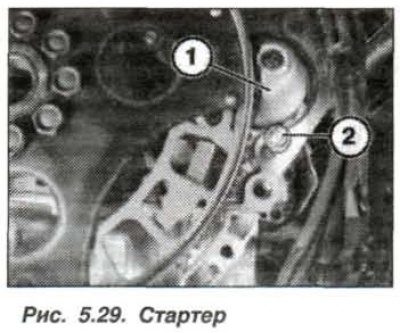
Fix the starter (1, Fig. 5.29) using the gearbox bolt (2) to prevent it from falling out.
Loosen the threaded connection of the power steering oil supply line, put it forward in the engine compartment and take measures to prevent the oil line from falling. Remove the power steering pump. To prevent the pump from falling, secure it to the anti-roll bar with a bandage or wire clip.
Remove the fuel supply line from the distribution line and plug the hoses using the devices "13.5.281" and "13.5.282". Collect the leaked fuel. Loosen the clamp and move the liquid drain hose away from the heater.
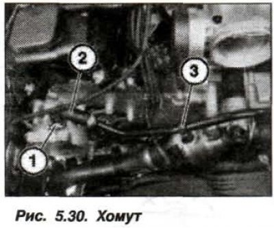
Loosen the clamp (1, Fig. 5.30), disconnect the vacuum line (2) from the vacuum pump. Remove the vacuum line from the holder (3).
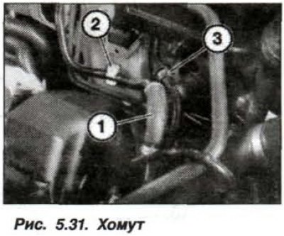
Release the vacuum line (1, Fig. 5.31) from the holder (2) and move it to the side. Unlock and remove the fuel tank ventilation valve (3).
Disconnect the engine wiring harness from the control electronics compartment, disconnect the "+" wire from the "+" terminal of the battery. Disconnect the branch of the wiring harness from the gearbox and remove the oxygen sensors in the exhaust gas, secure them to the engine.
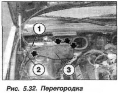
Remove the partition (3, Fig. 5.32), to do this, it is necessary to release the hoses and wires from the clamps, disconnect the shock absorber (1), separate the wire harness (2), unscrew the nut and remove the bolts.
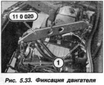
Install the "11.0.020" device on the engine and hoist (Fig. 5.33). Unscrew the upper nuts of the engine mount cushions on the left and right front side members of the body. Remove the jumper connecting the engine to the body "ground".
Make sure all hoses, lines and wiring harnesses connecting the engine to the engine compartment are disconnected, paying particular attention to:
- fuel lines near the cylinder head;
- air conditioning compressor;
- air conditioner compressor pipes;
- air conditioner condenser;
- exhaust manifold;
- front axle gearbox;
- steering shaft.
Smoothly lift the engine with a hoist (crane) and remove it from the compartment, making sure not to damage adjacent structures if they are accidentally touched. For further work with the engine, it must be moved and installed on a special workbench.
The engine should be installed on the vehicle in the reverse order, while checking the engine mounts, coolant, oil and fuel hoses for porosity, delamination and cracks. Check for the presence of centering bushings for connecting the engine to the gearbox. If defects are found, replace the parts with new ones.
Caution! There is a risk of damage to the automatic transmission pipelines and hydraulic drive oil lines.
When installing the stiffening plate, be sure to check for the presence of spacer washers. The process of tightening the new bolts for its fastening consists of two steps - tighten with a torque of 56 N·m (5.6 kgf·m) + turn by an angle of 90°.