
- power loss;
- drop in coolant level;
- drop in oil level;
- the presence of coolant in the oil;
- the presence of oil in the coolant;
- foaming coolant;
- lack of compression in adjacent cylinders.
Replacing the sealing gasket of any of the cylinder heads includes three steps - removing the cylinder head, replacing the sealing gasket and installing the cylinder head. They are described separately for the right and left heads. If it is necessary to replace the gaskets on both heads, start work from the left cylinder head.
Replacing the left cylinder head
Attention! To remove the exhaust manifolds, it is necessary to fix the engine in the installation position using the tool «00.0.200», and then lower the front axle beam.
Removal of the left cylinder head must be carried out in the following order.
Prepare fixture «00.9.120». Lower the front axle beam and remove the left exhaust manifold. Temporarily reinstall the front axle beam in its original position and remove the fixture for fixing the engine in the installation position.
Remove the coolant drain plug on the left side of the cylinder block. Drain the liquid and send it for disposal.
Remove the ignition coils for cylinders 5-8. Remove the left eccentric shaft drive motor and the left cylinder head cover (see above).
Remove intake duct (collector) and left timing case. Disconnect the ALs and set aside the engine wiring harness. Unscrew spark plugs for cylinders 5 to 8. Detach atmosphere hose from cylinder head.
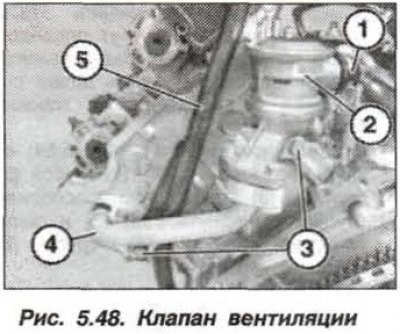
Disconnect the hose (1, fig. 5.48) from shutoff valve (2). guide tube (3) do not remove the oil dipstick.
Remove left intake and exhaust VANOS control units from cylinder head.
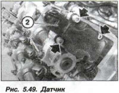
Loosen the bolts (arrows, fig. 5.49) and remove the sensor (2) position of the eccentric shaft.
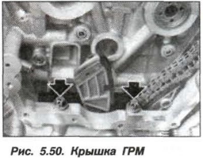
Disconnect the chain guide from the block head. Remove bolts (arrows, fig. 5.50) fastening the timing cover to the cylinder head.
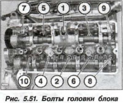
Loosen the cylinder head bolts in sequence 10-1 (pic. 5.51). Unscrew the bolts, remove the cylinder head and its sealing gasket.
Attention! Removed bolts and cylinder block gasket must no longer be used to install the cylinder head.
Installation of a head of the block of cylinders is necessary for carrying out in a following order.
Clear sealed (docking) surfaces on the timing cover, engine head and cylinder block using only a hardwood scraper for this purpose (oak, hornbeam, beech). When doing this, make sure that seal residues do not get into the air, oil and coolant channels.
Blow compressed air through the threaded holes in the cylinder block and cylinder head of the engine to remove traces of fluid (oils). The presence of liquid leads to cracks and incorrect determination of the tightening torque of the bolts.
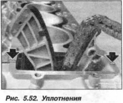
At the junction of the cylinder head with the timing case cover, apply an elastic sealing compound such as Drei Bond 1209 (arrows, fig. 5.52).
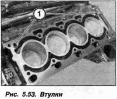
Check centering sleeves (1, fig. 5.53) for damage and correct installation. Replace the cylinder head gasket by installing it on the dowel sleeves.
Attention! For cylinder head with sealed surface treatment. install thicker (by 0.3 mm) sealing gasket.
Do not lubricate the surface of the new engine cylinder head bolts and do not wash off their coating. Insert new cylinder head bolts and tighten them by hand, crosswise, in the order of 1-10 (see fig. 5.51).
Using a manometric wrench and tool «00.9.120», tighten new bolts (M10) fastening of a head of the block of cylinders in sequence 1–10 (pic. 5.51) in three consecutive steps:
- 1st step - tighten with a torque of 30 Nm (3.0 kgf·m);
- 2nd reception - tighten by an angle of 90°;
- Step 3 - turn 90°.
Insert and tighten the bolts securing the timing cover to the cylinder head (arrows, see fig. 5.50).
Install the chain guide bolt and tighten it.
Install sensor (2) eccentric shaft (see fig. 5.49). Install left-hand VANOS control units inlet and outlet.
Assemble the engine, while replacing the bolt gasket (M14x1.5) drain hole of the engine block, and tighten it with a torque of 25 Nm (2.5 kgf·m). Fill with coolant. Bleed the cooling system and check for leaks.
Replacing the right cylinder head
Attention! To remove the exhaust manifolds, it is necessary to fix the engine in the installation position using the tool «00.9.120», and then lower the front axle beam.
Removal of the left cylinder head must be carried out in the following order.
Prepare fixture «00.9.120», lower the front axle beam. Remove the right exhaust manifold and again, temporarily, install the front axle beam in its original place. Remove the fixture for fixing the engine in the installation position.
Remove the coolant drain plug on the left side of the cylinder block. Drain it and send it for recycling. Remove the ignition coils for cylinders 1-4. Remove the right eccentric shaft drive motor.
Remove the right cylinder head cover and remove the intake duct (collector). Remove the right timing cover, disconnect the ALs and set aside the engine wiring harness. Remove spark plugs for cylinders 1-4. Remove the atmospheric pressure hose from the cylinder head.
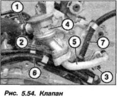
Disconnect the hose (1, fig. 5.54) from shutoff valve (2). Behind the pipe (5) bolt (3) bushing is fixed. Remove bolt (3) and remove the check valve (4), pipe (5) and spacer bushing.
Remove right intake and exhaust VANOS control units from cylinder head.
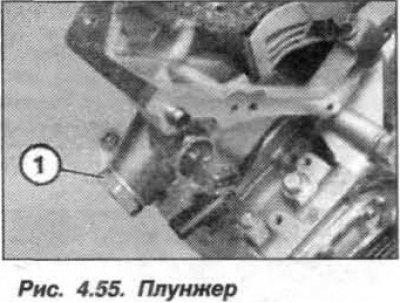
loosen the plunger (pic. 5.55) chain tensioner by 1–1.5 turns.
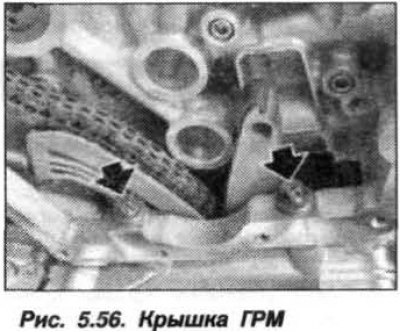
Loosen the screws and remove the eccentric shaft position sensor. Disconnect the chain guide from the block head. Remove bolts (arrows, fig. 5.56) fastening the timing cover to the cylinder head.
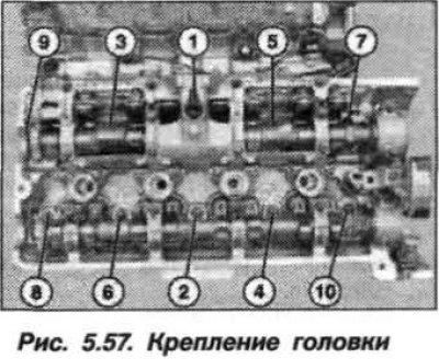
Loosen the cylinder head bolts in sequence 10-1 (pic. 5.57) one turn and remove the screws.
Attention! Removed bolts and cylinder block gasket must no longer be used to install the cylinder head.
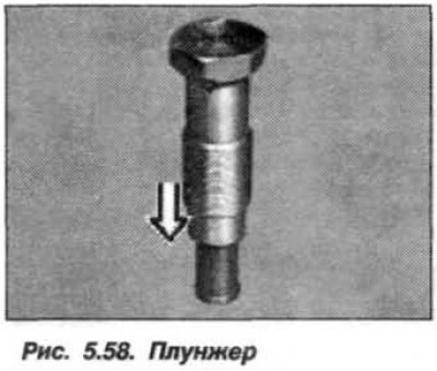
Remove the cylinder head. Remove the cylinder head gasket. Remove the chain tensioner plunger. Install plunger (1, fig. 5.58) chain tensioner on a flat pad and slowly carefully compress. Repeat the process twice.
The installation of the cylinder head must be carried out in the same order as for the left head of the block, while it is necessary.
Replace tensioner plunger o-ring. Install plunger (1) and tighten it until the heads of the mounting bolts fit.
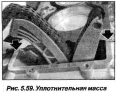
At the junction of the cylinder head with the timing case cover, apply an elastic sealing compound such as Drei Bond 1209 (arrows, fig. 5.59).
Check centering sleeves (1, fig. 5.60) for damage and correct installation.
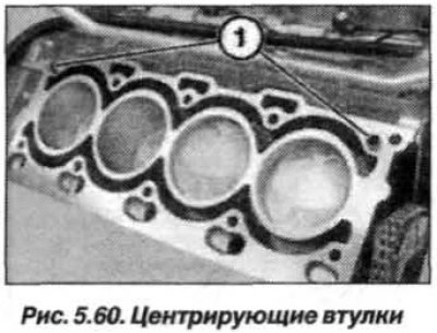
Replace the cylinder head gasket by installing it on the dowel sleeves.
Attention! For a cylinder head that has undergone sealing surface treatment, install a thicker (by 0.3 mm) sealing gasket.
Insert and tighten the bolts securing the timing cover to the cylinder head (arrows, see fig. 5.56).
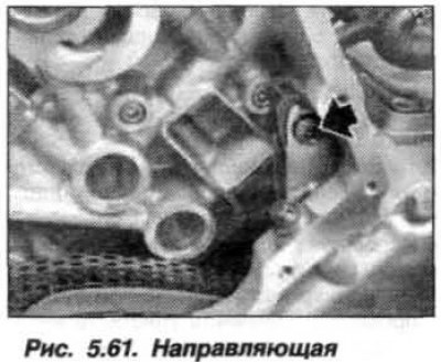
Install the chain guide bolt (arrow, fig. 5.61) and tighten it.
Tighten plunger (1, M22x1.5; see fig. 5.55) chain tensioner torque 65 Nm (6.5 kgf·m).
Install right intake and exhaust VANOS control units.
Assemble the engine, at the same time, replace the bolt gasket (M14x1.5) drain hole of the engine block and tighten it to 25 Nm (2.5 kgf·m). Fill with coolant. Bleed the cooling system and check for leaks.