
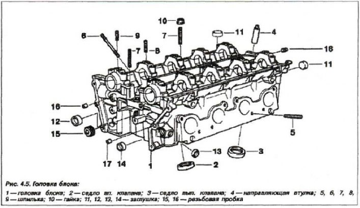
cylinder head (pic. 4.5) cast from aluminum alloy. It has two camshafts on plain bearings, intake and exhaust valves with their own closing springs. The valves move in pressed guides. The valve seats are pressed into the cylinder head. The camber angle is 39.5°. Valves are driven by camshaft cams through cylindrical hydraulic tappets (hydraulic pushers), valve clearances are compensated automatically and there is no need to adjust them. Oil channels are made in the cylinder head to supply hydraulic pushers and other elements with oil.
Permissible Warpage (flatness) the mating surface of the head with the cylinder block for all engines is not more than - 0.03 mm.
Rated/Minimum Head Height Series Engines «M62» 140.0 / 139.70 mm respectively.
Cylinder head gasket
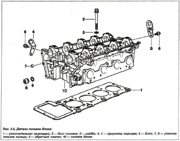
Pad (1, fig. 4.6) cylinder head made of synthetic materials (asbestos-free) with metal edging holes for cylinders.
The gasket is installed with a label «Oben» («Top») to the cylinder head. The thickness of the new gasket is 1.2 mm.
After grinding the cylinder head, install a repair size gasket on the engine, 1.5 mm thick (+0.3 mm).
Valve seats
valve seats (see fig. 3.5) are made of austenitic powder metallurgy steel and cannot be replaced.

1 - angle of the working chamfer; 2 - outer angle of correction; 3 - internal angle of correction, 4 - circular diameter of the bearing surface of the valve seat; 5-width of the working chamfer of the valve seat
If there are signs of burning or wear that cannot be removed by grinding, the entire cylinder head is replaced. In this case, it is necessary to maintain the maximum allowable size. If this size is exceeded, then the reliability of gap compensation during the operation of hydraulic pushers is violated. The valve seat is lapped (being repaired) until a reliable valve spot is obtained. The valve seats have an additional narrowing - the angle of external correction, and during processing it is necessary to maintain it - 15°.
The technology for lapping valve seats is identical for all gasoline engines.
Valve seat specifications
| Parameters | Valve seat | |
| inlet | prom | |
| Valve seat diameter, mm | ||
| - nominal | 34,5 | 30,0 |
| - admission | from 0.00 to 0.025 | |
| Working chamfer angle, degrees | 45 | 45 |
| Correction angle, outer | 15 | 15 |
| Correction angle, internal | 60 | 60 |
| Chamfer Width (B44), mm | 1,25±0,25 | 1,65±0,35 |
| Chamfer Width (B46), mm | 0,95±0,30 | 1,50±0,35 |
Valve guides
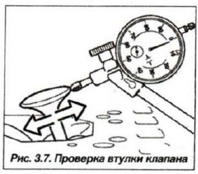
The valve guides are made from a special bronze-based brass alloy and are pressed into the cylinder head. The parameters of the guide bushings of the intake and exhaust valves are the same. Check the gap using a tool (see fig. 3.7).

Maximum allowable clearance (during operation), between the valve stem and guide sleeve, is measured by the maximum displacement of the valve head when the valve stem is flush with the top edge of the guide. Wherein:
Inner diameter, mm:
- nominal - 6.00
- 1st repair size - 6.10
- 2nd repair size - 6.20
Execution tolerance - from 0.00 to + 0.015
Maximum stem/sleeve clearance - 0.50
Valves
The valves are hardened rods made of special stainless steel with chrome plating, and are located in the block head in a V-shape, at an angle of 39.5°. They are driven by overhead intake and exhaust camshaft cams via hydraulic tappets. The drive system is made according to the DOHC scheme. The parameters of the engine valves are given in the table.
Minimum height of the cylindrical part of the valve disc «b» (see fig. 5.6) - 0.5 mm.
One of the main indicators of engine wear depends on the state of the valve mechanism - the amount of compression in its cylinders, which is checked by a special device - a compression gauge (see fig. 3.31), installed in the spark plug hole.
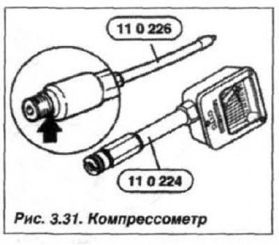
The rules for its installation and taking measurements are given in the instructions for the device and are described below. Instrument reading for a new engine - 12-14 bar (kgf/cm2), at limit wear, this value must be at least - 10.0 bar. The difference in pressure between the cylinders of the same engine must not exceed 1.5 bar. If the difference is more than 1.5 bar or the pressure is less than 10.0 bar, then this indicates increased wear of the piston rings, cylinder mirrors, valves. Such an engine must be removed and repaired.
Engine valve parameters
| Valve parameters | Engine Model | |
| М62В44 | М62В46 | |
| Inlet valves | ||
| Plate diameter, mm | 35,00 | 35,00 |
| Head diameter tolerance, mm | from 0.00 to -0.016 | |
| Rod diameter, mm | ||
| - nominal | 6,00 | |
| – 1st repair | 6,10 | |
| – 2nd repair | 6,20 | |
| - permission to perform | -0.025 to -0.040 | |
| Gap between guide bushings and valve stems, mm* | 0,5 | |
| Exhaust valves | ||
| Head diameter, mm | 30,50 | 30,50 |
| Head diameter tolerance, mm | from 0.00 to -0.016 | |
| Rod diameter, mm | ||
| - nominal | 6,00 | |
| – 1st repair | 6,10 | |
| – 2nd repair | 6,20 | |
| - permission to perform | -0.045 to -0.055 | |
| Gap between guide bushings and valve stems, mm* | 0,5 | |
* The measurement procedure is shown in fig. 3.7.
Valve springs
Valve springs (see fig. 4.12) are designed to ensure a hermetic fit of the valves on the saddles.
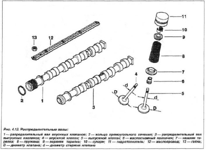
Each inlet and outlet valve has one spring of complex shape - cylindrical-conical. The springs are identical for both intake and exhaust valves.
Hydraulic tappets
Hydraulic tappets are installed directly in the body of the cylinder head. The valves are driven by camshaft cams through hydraulic tappet plungers. The gaps in the valve drive mechanism are compensated automatically by hydraulic tappets. The design and principle of operation of these hydraulic pushers is similar to the M54 engine (see fig. 3.9).
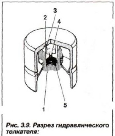
1 - pusher cylinder; 2 - groove; 3 - plunger; 4 - check valve; 5 - spring
The free travel of the pusher pistons is not more than 0.1 mm.