
Attention! Fuel in the lines is under pressure, spilled fuel must be collected and sent for disposal.
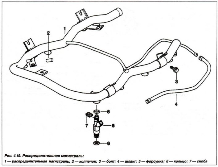
Replacement of the distribution line (1, see Fig. 4.19) the fuel system assembly must be carried out in the following order: Prepare a container and rags to collect spilled fuel, turn off the ignition and remove the soundproof casing.
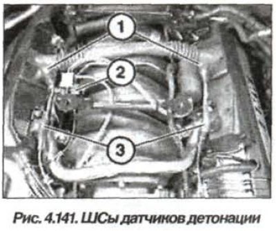
Mark the SS (1, Fig. 4.141) knock sensors. Disconnect IIIIC (2) from the switching EMC. Disconnect the camshaft position sensor terminals (3) from the electrical installation board. Remove the plugs on the left ignition coil housing and disconnect the terminals from the ignition coils.
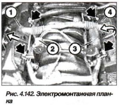
Unscrew the nuts (arrows, Fig. 4.142) and disconnect the electrical mounting strip from the injectors. Put aside the switching EMC (2) together with the holder. Disconnect the vacuum line from the vacuum cavity (3). Put the vacuum cavity (3) aside together with the holder. Disconnect the electrical mounting strip (4) from the injectors (nozzles) and put it aside.
Note: When disconnecting pipes and hoses, fuel will leak out, collect it and send it for disposal.
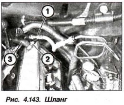
Disconnect the fuel line (1, Fig. 4.143) from the distribution line (ramp). Loosen the clamp (2) and disconnect the hose (3).
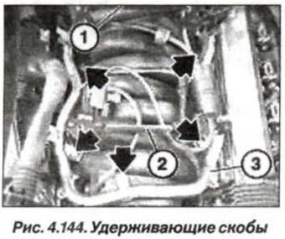
Unscrew the nuts (arrows, see Fig. 4.144) and remove both retaining brackets (1 and 2). Remove the distribution line (3) with the injectors by moving it upwards and remove it together with the injectors (injectors). Remove the fuse clips and remove the injectors from the distribution line.
Before installing the injectors, check their O-rings. To facilitate the installation of the distribution line, lubricate the O-rings (circular cross-section) fuel injection injectors (nozzles) with a thin layer of lubricant such as "technical petroleum jelly".
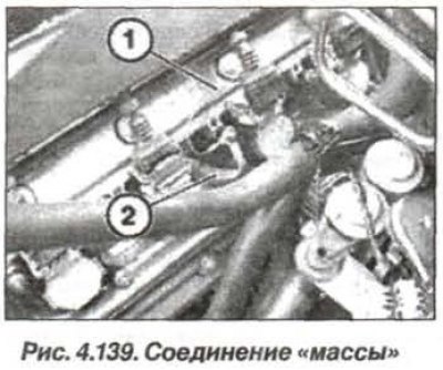
When installing a narrow (see fig. 4.139) and a wide jumper connection to the ground, secure them with a bolt to the ignition coil of the 7th cylinder.
Read information from the fault memory of the ECU-KSUD of the "DME" system. Erase information from the fault memory.
[The original article is available on the website www.bmwman.ru]