
Removing the intake manifold must be carried out in the following order.
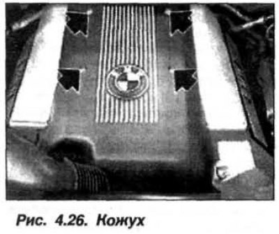
Disconnect «–» AB terminal and remove the heater baffle, remove the soundproof casing of the air flow supply (see fig. 4.26).
Remove the casing covering the engine ignition coils, for which purpose remove the plugs, unscrew the bolts located under them. Disconnect plug connection (ShS) ignition coils.
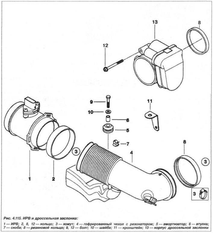
Remove the bellows from the throttle shaft and the air filter housing together with the air flow meter (see fig. 4.115).
unscrew «+» AB wire from output «pluses» AB on the front panel in the engine compartment. Isolate and remove «+» AB wire and put it aside.
Disconnect plug connectors (ShSy) branches of the engine wiring harness and move the harness to the side along with the cable boxes.
Disconnect vacuum air control hose and vacuum hose from throttle body.
Attention! When carrying out work on fuel pipelines, ensure the collection of escaping fuel and its further disposal.
Have a clean rag ready to collect escaping fuel and follow the instructions for removing and installing fuel hoses. Remove the fuel supply line from the distribution line and plug the ends of the hose using the tool «13.5.281» and fixtures «13.5.282». Collect leaked fuel with a rag and send it for disposal.
Loosen the clamps and remove the hose (1, fig. 4.109) from the crankcase ventilation pipes from the cylinder head cover on the side of cylinders 5 - 8.
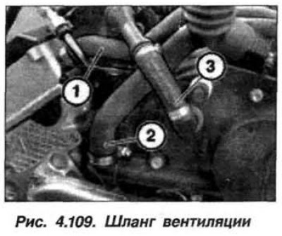
Loosen the clamps and remove the hose (2) from the crankcase ventilation pipes from the oil separator of the ventilation system. Remove connector (3) brake booster vacuum line.
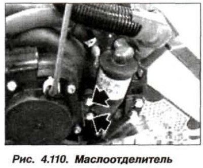
Loosen the bolts (arrows, fig. 4.110) and remove the crankcase ventilation oil separator from the rear cover.
Attention! Under the intake manifold there is an oil drain pipe fixed on its rear cover. Before unscrewing the fastening of the intake manifold, it must be disconnected.
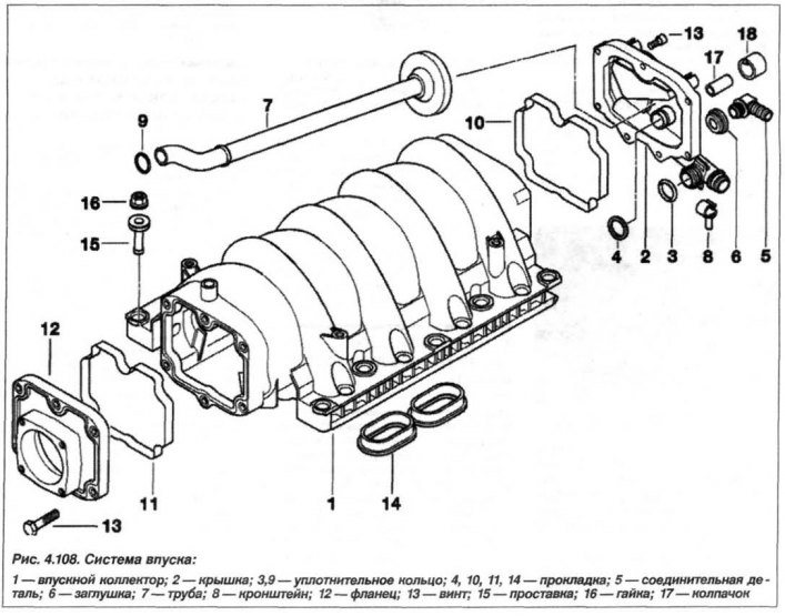
Loosen the nuts (16, see fig. 4.108) left and right and remove spacer bushings (15).
Raise the intake manifold by 7–10 cm and move it carefully to one side. Disconnect the oil drain line from the rear cover. Remove the intake manifold towards the top.
Close all intake manifold and cylinder head openings. The ingress of foreign bodies into the intake manifold can lead to engine failure.
The crankcase ventilation pipe is fixed to the intake manifold with a lug (1, fig. 4.111) and locked with a locking lug (2).
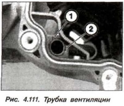
Carefully press in the locking lug (2) and pull the crankcase breather pipe out of the hole in the intake manifold and remove it completely.
If necessary, remove the throttle (13, see fig. 4.115).
Remove the front (12, see fig. 4.108) and back (2) intake manifold covers.
Installation of the intake manifold should be carried out in reverse order, if necessary.
Check the integrity of the gaskets (10, 11, 14, see fig. 4.108) and make sure they are in the correct position. Replace the gaskets under the front and rear intake manifold covers. Replace gaskets and insert tube (7) crankcase ventilation systems.
Check the position of the latch (1, fig. 4.111) and latch actuation (2) in the intake manifold. Check the oil drain line for damage.

If necessary, replace it and the abrasion protection gaskets. Ensure that the oil line is laid without kinks.
Remove the previously installed plugs from the intake manifold and cylinder heads, replace the gaskets (14, see fig. 4.108).
Check and, if necessary, replace the elastic spacer bushings (2, fig. 4.112), thanks to which the vibration from the cylinder head is not transmitted to the intake manifold.
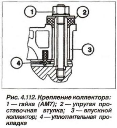
Replace seals (4). Install intake manifold. Install flexible spacers (2) on the outer studs, on the right and left of the intake manifold. nuts (1) Tighten fasteners by hand and align intake manifold.
Install the remaining elastic spacer bushings and evenly, crosswise, tighten the nuts (1) intake manifold mounting torque 15 Nm (1.5 kgf·m). Assemble the engine.