
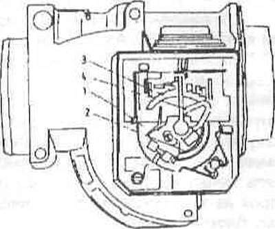
Air flow meter of early car models
1 - toothed crown;
2 - return spring;
3 - sliding contact ridge;
4 - sliding contact of the potentiometer.
The air flow meter housing contains a flap that deflects at a certain angle when air passes through it. The angular position of the flap is a measure of the amount of air passing through.
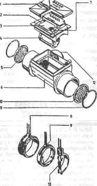
Air flow meter for late model cars
1 - lid;
2 - main board;
3 - switch;
4 - inner tube;
5 - protective grille;
6 — body;
7 - Power buffer transistor;
8 — measuring resistance;
9 - element with glow wire;
10 - protective net;
11 - retaining ring;
12 — connector;
13 — temperature compensation resistance.
Air is drawn into the engine through the air filter and passes through a hot mesh air flow meter (late model cars). The air flow meter housing contains a thin, electrically heated plate, which is cooled by the air passing through. The electronic control regulates the heating current so that the temperature of the plate remains constant. If, for example, the amount of incoming air increases, the heated plate will tend to cool down. Because of this, the heating current immediately increases so that the temperature remains the same. The DME determines the engine load based on the fluctuations in the heating current.
The control unit controls the injection time and, accordingly, the amount of fuel injected according to the amount of air and the engine speed. More fuel is injected when the injector is opened longer. Additional devices and sensors also ensure precise determination of the amount of fuel in extreme situations.
Fuel injection is sequential. This means that the injectors are controlled individually and inject fuel in accordance with the firing order to the engine's intake valves. By selecting the injection moment and the opening duration of the injectors, the engine's power and exhaust toxicity can be precisely controlled. The engine responds very quickly to the gas pedal.
The throttle potentiometer is located directly on the throttle shaft. It informs the control unit of the actual position of the throttle valve. Thanks to this, the engine braking mode is controlled, i.e. when the throttle valve closes and at the same time the number of revolutions reaches a certain value, the control unit stops supplying fuel to the engine.
The fuel pump relay is located in the relay box behind the left front shock absorber strut. It supplies voltage to the fuel pump. A safety circuit interrupts the voltage supply when the engine is not running, for example, if it suddenly stops.
The instantaneous position of the engine crankshaft and its speed are determined by two inductive sensors: the speed sensor and the reference mark position are located on the crankshaft pulley. The cylinder identification sensor is located at the front of the engine in the timing chain cover. Two lambda probes measure the oxygen content in the exhaust gas flow and send corresponding voltage signals to the control unit. By analyzing the signals, the control unit changes the air/fuel ratio so that the exhaust gases are optimally burned in the catalytic converter.
The idle speed control valve regulates the amount of air in the idle mode that bypasses the throttle valve. This ensures a stable idle speed regardless of how much additional load, such as power steering or air conditioning compressor, is connected at the time.
The electromagnetic valve for ventilation of the fuel tank is controlled depending on the engine operating mode. Fuel vapors in the tank are collected in the activated carbon filter and fed to the engine for afterburning through the valve. Thus, fuel vapors are mostly used usefully thanks to the filter and do not escape into the atmosphere.
The variable valve timing system with camshaft, abbreviated as VANOS, rotates the camshaft for the intake valves depending on the engine speed and load with the engine oil pressure relative to the drive sprocket in such a way that optimum valve timing is achieved in terms of idling comfort, torque and fuel consumption. The DME regulates the oil flow to the actuator via an electrically controlled valve.
The high voltage monitoring system switches off the DME if the voltage value is too low (for example, in case of damage to high-voltage wires), and the engine cannot be started. This prevents damage to the catalytic converter.
Management of other control systems (ABS, ASC, gearbox control) is carried out using CAN, a special data processing system. Among other things, the advantage of this system is that the engine wiring harness has fewer wires, and the car is less susceptible to failure due to malfunctions of individual control units.