
Remove driven gear.
Squeeze out the axis of the satellites using the tool.
Turn out satellites with a flange of a leading shaft.
Remove the drive shaft gears with Belleville springs and spacers.
Install new axle gears with belleville springs and spacers. The inner bulge of the Belleville spring faces the differential box.
Align the driveshaft gears with the driveshaft flange.
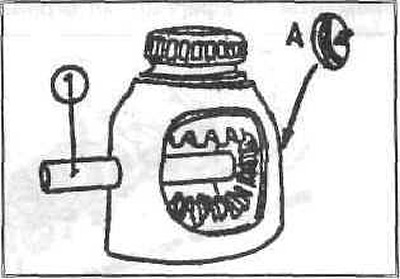
Insert stop into drive shaft gear.
Screw the threaded plate with the spindle.
While tightening the spindle, open the axle gears until the driven flange rotates
Insert satellites exactly opposite each other.
By turning the flange of the drive shaft, bring the satellites to the installation position.
Remove stop, threaded plate, spindle.
Subsequent work should be done with a hydraulic press.
Check the correct position of the retaining ring (A).
Insert the tool from the side without the circlip.
Slide the pinion axle with a large notch onto the tool and press it in.
Attention: If the retaining ring snaps into place, the press-in pressure will increase greatly.
Stop pressing immediately, because. otherwise the retaining ring will break.
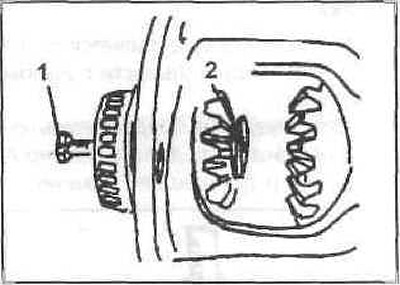
To measure cup spring tension, install a threaded plate (2) and bolt (1), screw the bolt by hand.
Fix the measuring device with the holder on the differential box.
Set the instrument to zero on the locked gear.
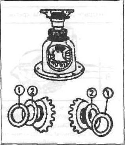
Tighten the spindle until the belleville spring (1) will not be on the block.
Take instrument readings.
Loosen the spindle, rotate the shaft gear and repeat the measurement in a few more places.
Spring clearance should be 0.03-0.1 mm.
Repeat measurements on the opposite gear of the shaft.
Correct the gap with expansion washers (2).