
Press the pulse sensor sprocket if necessary.
Remove the tapered roller bearing with a puller.
Remove the driven bevel gear.
Press in a new tapered roller bearing using a bushing.
Remove the seals from both bearing caps.
Press out the outer bearing races with a tool and a puller sprocket.
Caution: The removable sprocket must be locked into the bearing.
Press in new bearing outer races using the tool.
If only the differential bearings are being replaced, the bevel gear pinion may remain installed and the differential case inserted without the driven bevel gear to determine the size of the compensation washers.
Lubricate the bearings well with oil and let it drain.
Install the side bearing caps with their compensation washers, but without the rings first.
Tighten the bearing cap bolts on the driven gear side. Note the installation position of the cap.
The compensation hole in the installation position must always face upwards.
The axial stress of the differential box (5000 N) can be determined through the turning resistance force.
Tighten the second bearing cap bolts so that the differential can rotate easily.
Place the flange on the side tightened to a certain force and secure it with a clamp and welded nut. Use a dynamometer to measure the resistance force to turning at 50 rpm.
The turning force depends on the bearing (manufacturer) and is 1.24-2.8 Nm.
If, despite the covers being installed, the required force is not achieved, thinner compensation washers should be installed against the differential gear until the specified force is achieved.
The opposite should be done if the force is achieved even when the caps are not tightened.
Remove the differential box, position the side covers and the selected compensation washers.
Install the driven bevel gear.
Insert two threaded guide pins into the driven gear threads diagonally.
Heat the driven gear to 100°C and check with a thermocouple.
Install the driven gear, insert the bolts. Observe the tightening torque.
Tighten the bolts in a cross pattern.
Install the differential with the driven gear.
Install the side cover as indicated with the corresponding bolt.
Adjust the lateral clearance in the gear engagement using a device. It should be 0.06-0.13.
Check the engagement pattern of the main gear teeth. To do this, lubricate the driven bevel gear with lead oxide to determine contact, and turn it in both directions under load.
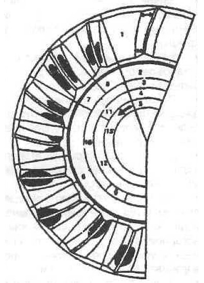
Determination of the engagement of the main transmission gears by the contact patch
1 - the height of the teeth on the outer diameter is greater than on the inner one (arrows);
2 - type of spot - load;
3 - clearance in engagement;
4 - type of spot;
5 - direction of rotation;
6 - no load;
7 - with load;
8 - no load;
9 - very small;
10 - correct;
11 - correct;
12 - incorrect;
13 — back.
Adjustment of the lateral clearance is possible by changing the thickness of both compensation washers.
The total thickness of the compensation washers cannot be changed. If one washer is made thinner, the other must become thicker by the same amount.
An axial shift of the driven bevel gear by 0.01 mm means a change in the lateral clearance of 0.0076 mm.
Insert the seals and rings into the side covers as described earlier.
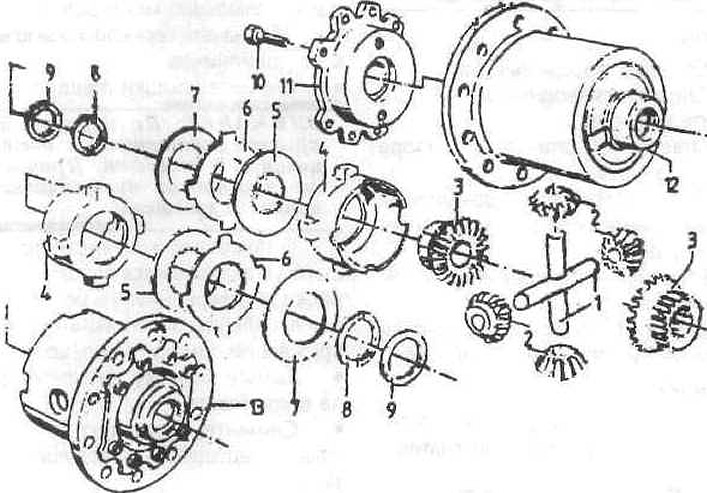
Elements of the main transmission of the rear axle
1 — differential axle;
2 - conical satellites;
3 - axle shaft gears;
4 - pressure ring;
5 - internal slats;
6 - external slats 1.9 mm, 2.0 mm, 2.1 mm;
7 - disc spring;
8 - adjusting washer;
9 - disc spring;
10 - cylindrical bolt;
11 — case cover;
12 — differential housing;
13 - limited slip differential.
This article is based on data from the website: BMWman