
If the installed boost air hoses are not degreased and are damp, this may lead to turbocharger failure.
1. Disconnect the negative cable from the battery.
2. Remove the lower engine compartment cover
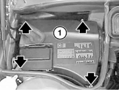
3. Loosen the bolts and remove the EC compartment cover).
4. Disconnect the connector.
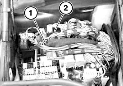
5. Disconnect all connectors of the electronic units (1 and 2) of the engine management system.
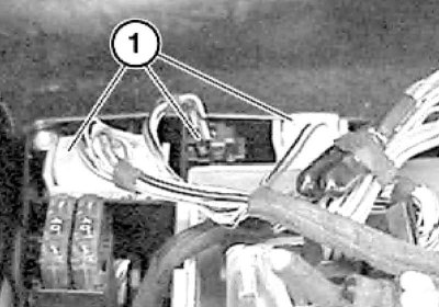
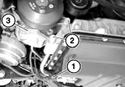
6. Disconnect the glow plug relay connectors (1 and 2).
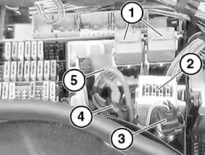
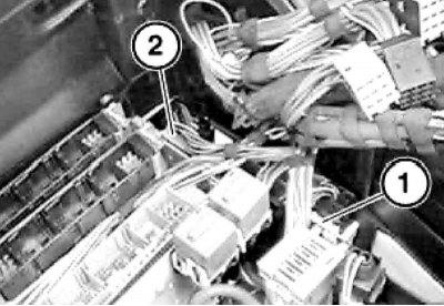
7. Remove the relay (1) with the base and the fuses (2). Disconnect the connector (3), remove the protective cap (4), loosen the nut and disconnect the positive cable (5) of the battery.
8. Loosen the nut (1), press the retainer (2) and disconnect the diagnostic connector (3).
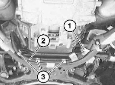
9. Remove the seal (1) and pull out the wiring box (2) in an upward direction.
10. Press the clamps (1), remove the cover of the wiring box (2), pull the wiring harness out of the box and secure it to the engine.
When installing, pay attention to the guides (3).
11. Remove the positive battery cable terminal cap.
12. Give the nut.
13. Loosen the clamps (1) and release the positive wire (2) from the holders (3).
14. Remove the transmission oil line bracket from the engine oil pan. Loosen the positive battery cable clamps.
15. Remove AT (see chapter Automatic transmission).
16. Remove the engine cooling system radiator (see chapter Engine cooling, heating, ventilation and air conditioning systems).
17. Press the brake pedal several times to reduce the vacuum in the brake booster.
18. Press the lock (1) and at the same time disconnect the vacuum hose together with the connection (2).
When installing, check the sealing ring of the connection and replace it if necessary. Disconnect the vacuum hoses (2, 3 and 5) from the vacuum line (6).
Vacuum hoses
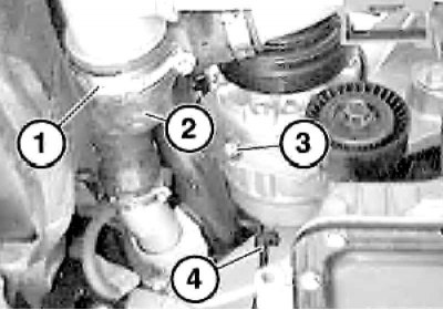
19. Remove the bolts (1) and move the vacuum line to the side (2). Press the retainer (1) and disconnect the fuel line (3) from the preheating valve. Open the clamp (2), remove the fuel line (3) and secure it to the engine. Disconnect the connector (4), press the retainer (5), disconnect the fuel supply line (6) and secure it to the engine.
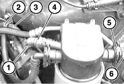
Fuel line connections
Collect any leaking fuel.
20. Loosen the clamps (1) and remove the right one (2) and left (3) pressure hoses for inflating air.
When installing, place the clamps in their original places.
The hoses must be dry and free of grease.
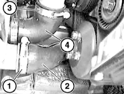
21. Loosen the clamps (1) and remove the pressure hose (2) assembly. Loosen the clamp (3) on the intercooler and remove the pressure hose (4) assembly with the pressure pipe.
The hoses must be dry and free of grease.
22. Loosen the clamp (1) on the intercooler and remove the pressure hose (2) together with the pressure pipe. Loosen the clamp (3) and move the pressure hose (4) to the side.
The hoses must be dry and free of grease.
23. Remove the A/C compressor drive belt tensioner (see section Removal and installation drive belts and their tensioners).
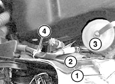
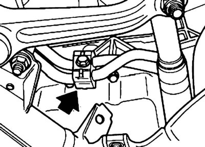
24. Unscrew the bolt (1) and loosen the clamp (2).
25. Disconnect the connector (1), unscrew the bolts (2), remove the power steering pump (3) from the upper section of the oil pan and secure the pump with wire to the front axle beam.
26. Unscrew the bolt (3) and release the wire (4) from the holder.
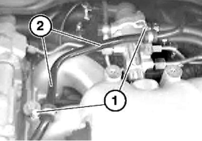
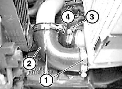
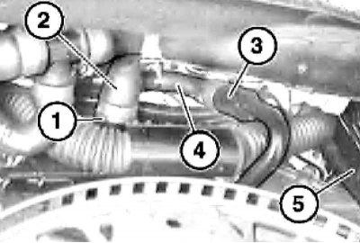
27. Loosen the clamp (1) and remove the charge air hose (2) together with the charge air line.
The hoses must be dry and free of grease.
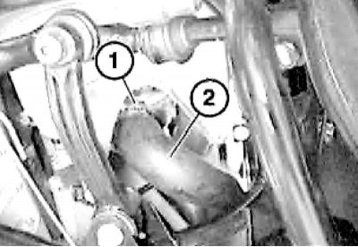
28. Disconnect the suction pipe (1) from the turbocharger and move it slightly to the side. Unscrew the bolts (2) securing the A/C compressor, lower the compressor down and disconnect the electrical wire from it.
Do not disconnect the A/C system pipes.
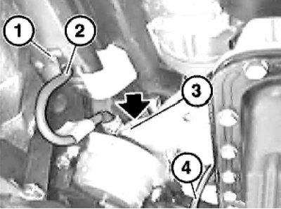
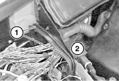
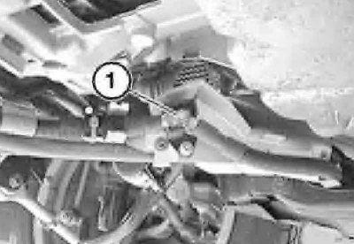
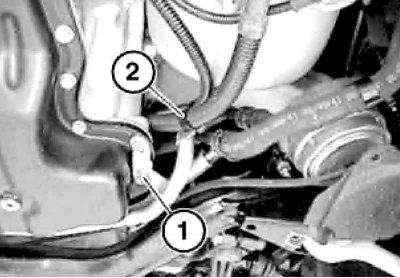
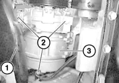
29. Loosen the nut (1) and remove the ground wire (2). Loosen the nut (3) of the engine mount cushion and disconnect the vacuum hose (4) from the adapter.
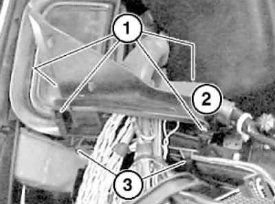
30. Release the fasteners (1 and 3) and disconnect the water hoses (2 and 4). Tie the AT wiring harness (5) to the turbocharger on the right side. Secure the positive battery cable behind the flywheel.
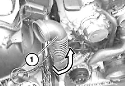
31. Slightly lift the engine by the lifting eyes and remove the suction pipe (1) in the direction indicated by the arrow.
32. Using a special lift, remove the engine upwards from the engine compartment by the front and rear eyes.
Be careful not to damage components in the engine compartment when lifting the engine.
33. Installation is carried out in the reverse order of dismantling the components.
34. After installation, before starting the engine, check the levels of the working fluids and adjust them if necessary.
35. After carrying out work between the fuel tank and the high-pressure fuel pump, the fuel supply system should be bled to avoid the high-pressure fuel pump running dry and being damaged. To remove air from the high-pressure fuel pump, perform the following operations:
- Disconnect the supply line from the fuel injection pump;
- Turn on the ignition;
- Wait until the fuel comes out without bubbles and turn off the ignition;
- Install the supply pipe with a new clamp.
36. Start the engine and check for fuel and fluid leaks, abnormal noises and vibrations.
37. Let the engine idle, then turn it off and check the fluid levels again.
[You can find the original version on the portal: BMWMAN.ru]