
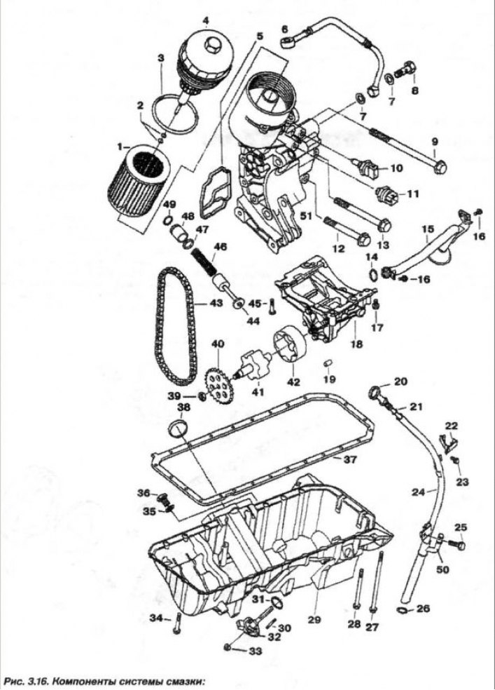
1 - replaceable element; 2 - ring (7.0x2.5); 3 - ring (91x4); 4 - filter cover; 5 - sealing gasket; 6 - oil pipeline; 7 - sealing ring (A14x20); 8 - hollow bolt; 9 - bolt (M8x100); 10 - oil temperature sensor; 11 - oil pressure sensor; 12 - bolt (M8x55); 13 - bolt (148x70); 14 - ring (20x3); 15 - suction pipe; 16 - bolt (M6x16); 17.45 - bolt (M8x55); 18 - oil pump; 19 - bushing; 20 - feeler gauge; 21 - ring (9x2.2); 22 - bracket; 23, 25, 27, 28, 34 - bolt; 24 - guide; 26 - ring (19.5x3); 29 - oil pan; 30 - pin (M6x30); 31, 35 - sealing ring; 32-oil level sensor; 33 - nut (M6); 36 - plug (M12x1.5); 37 - sealing gasket; 38 - mounting ring; 39 - nut (M10x1); 40 - asterisk; 41 - internal rotor; 42 - outer rotor; 43 - chain; 44 - control valve; 46 - spring; 47 - ring (17x1.8); 48 - spacer sleeve; 49 - retaining ring (2x1); 50 - oil separator hose branch pipe; 51 - oil filter housing
After the oil filter, a pressure reducing valve is installed, which, when the pressure increases above the set value, dumps excess oil into the oil bath (pan). When the filter is clogged, the bypass valve directs unfiltered oil directly into the pressure line. The opening pressure of the pressure reducing valve is 4.0 kgf/cm².
A check valve is installed in the oil filter nipple, which prevents oil from leaking out of the engine channels and hydraulic valve lifters after the engine is stopped. Purified oil flows through the pressure line and its branches to the main bearings of the crankshaft. Through inclined holes in the crankshaft body, oil flows to its connecting rod journals and is sprayed to the piston pins and cylinder mirrors. At the same time, engine oil flows through vertical channels to the cylinder head to the camshaft bearings, cylindrical hydraulic valve lifters, valve guides, chain tensioners and the mechanism for changing the position of the camshafts.