
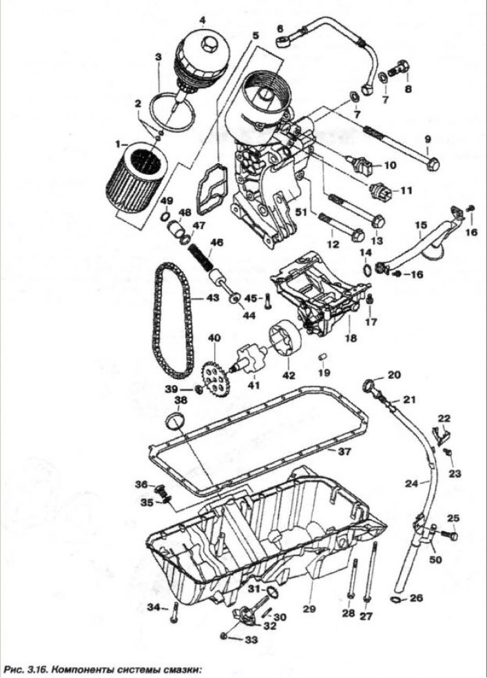
1 - replaceable element; 2 - ring (7.0x2.5); 3 - ring (91x4); 4 - filter cover; 5 - sealing gasket; 6 - oil pipeline; 7 - sealing ring (A14x20); 8 - hollow bolt; 9 - bolt (M8x100); 10 - oil temperature sensor; 11 - oil pressure sensor; 12 - bolt (M8x55); 13 - bolt (148x70); 14 - ring (20x3); 15 - suction pipe; 16 - bolt (M6x16); 17.45 - bolt (M8x55); 18 - oil pump; 19 - bushing; 20 - feeler gauge; 21 - ring (9x2.2); 22 - bracket; 23, 25, 27, 28, 34 - bolt; 24 - guide; 26 - ring (19.5x3); 29 - oil pan; 30 - pin (M6x30); 31, 35 - sealing ring; 32-oil level sensor; 33 - nut (M6); 36 - plug (M12x1.5); 37 - sealing gasket; 38 - mounting ring; 39 - nut (M10x1); 40 - asterisk; 41 - internal rotor; 42 - outer rotor; 43 - chain; 44 - control valve; 46 - spring; 47 - ring (17x1.8); 48 - spacer sleeve; 49 - retaining ring (2x1); 50 - oil separator hose branch pipe; 51 - oil filter housing
Remove the oil pan (29). Unscrew the nut (39, M 10x1.0), which has a left-hand thread. Remove the sprocket (40) of the oil pump drive together with the drive chain.
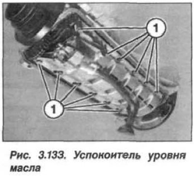
If the oil pump receiver is built into the oil level stabilizer, then it is necessary to unscrew the bolts (1, Fig. 3.133) and remove the oil pump together with the oil level stabilizer.
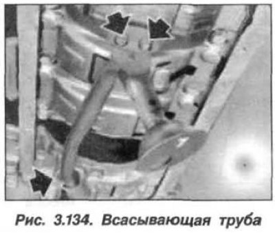
If the oil pump and oil level stabilizer are two separate parts, then unscrew the mounting bolts (3 pcs., arrows, Fig. 3.134) and remove the oil pump suction pipe.
Loosen the bolts (17 and 45. 4 pcs. see fig. 3.16) oil pump mounts and remove it.
Check the presence and technical condition of two installation (centering) bushings (19). When installing, replace the O-ring (14) of circular cross-section on the suction pipe. Tighten the oil pump mounting bolts to a torque of 20 N·m (2.0 kgf·m). Tighten the oil pump drive sprocket mounting bolt to a torque of 25 N·m (2.5 kgf·m).