
Cover the generator from contamination. Remove the heat exchanger of the "AGR" system. Unscrew the bolts securing the lifting eyes and remove them. Unscrew the screws and remove the return pipe.
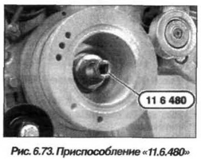
Using the device "11.6.480" (Fig. 6.73) and rotating the engine shaft clockwise, set the piston of the first cylinder to the TDC position at the end of the compression stroke. Remove the plug on the crankcase located below the starter. Using the device "11.2.300", block the engine crankshaft.
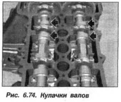
Check the position of the cams of the valve drive of the first cylinder, their tops (arrows, Fig. 6.74) should point to the right when looking in the direction of travel.
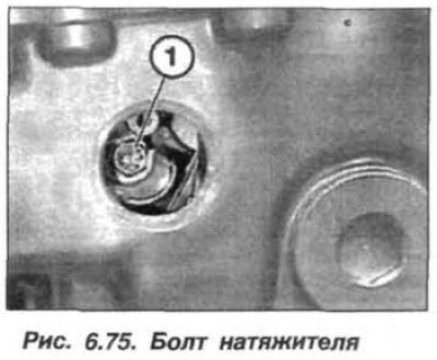
Unscrew the threaded plug (M30x1.0) and loosen the bolt (1, Fig. 6.75) hydraulic chain tensioner to relieve oil pressure.
Note: Be sure to lock the tensioner before removing the camshaft drive sprocket.
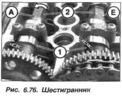
Using a key set on the Allen key (2, Fig. 6.76), slowly and carefully turn the intake camshaft (E) in the direction of engine rotation until the hydraulic chain tensioner is fully compressed.
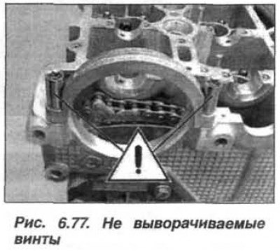
Insert the "11.3.340" tool into the tensioner (arrow, see Fig. 6.75) chain and lock it. Do not unscrew the screws indicated by the "!" sign (Fig. 6.77).
Remove the screws (1 and 6, Fig. 6.78). When unscrewing the screws (6) and (3) securing the camshafts, hold the camshafts from turning using the hexagon. Remove the gear (7).
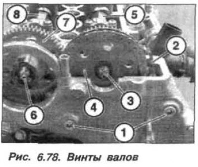
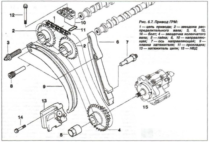
Remove the bolts (3 and 8, see Fig. 6.7) and remove the intake camshaft sprocket. Press the chain tensioner bar (9) down. Move the sprocket (1) with the drive chain (1) on it to the side. Remove the chain guide (6) upwards. Remove the tensioner bar (9) upwards. Move the drive chain (1) to the side and secure it with a bracket to prevent it from slipping. Remove the intake camshaft drive gear (2).
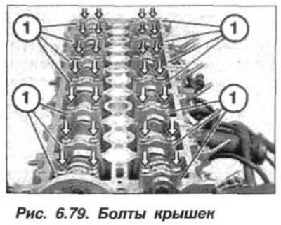
Loosen and unscrew the bolts evenly, in several steps, half a turn at a time (1, Fig. 6.79) fastening the camshaft bearing caps, moving from the edges to the middle.
Remove the intake and exhaust camshafts and carefully place them on a stand to the side.
Note: Used pushrods can only be used with the camshaft cams attached.
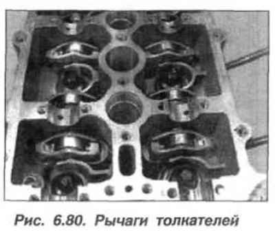
Remove the tappet levers one by one (Fig. 6.80) and check their rollers for ease of movement. The intake valve camshafts are marked "E", and the exhaust valves are marked "A".
The installation of camshafts must be carried out in the following order.
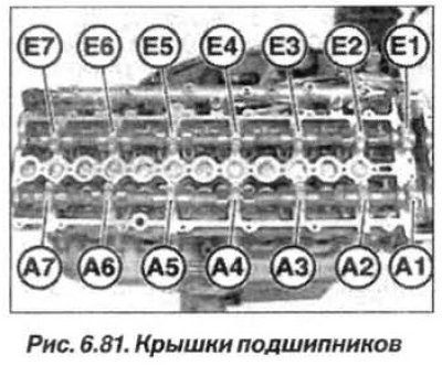
Check the technical condition of the camshafts and their caps, lay the shafts. The bearing caps (Fig. 6.81) of the intake camshaft are marked "E1–E7", starting from the exhaust side and the timing cover. The bearing caps of the exhaust camshaft are marked "A1–A7", starting from the exhaust side and the timing cover. Lay the bearing caps.
Adjust the intake and exhaust camshafts so that the cam lobe tops of both shafts (arrows, see Fig. 6.74) The 1st cylinder points to the right when looking in the direction of travel.
Caution! Due to the risk of damage to the camshafts, tighten the bearing caps evenly.
Evenly, in several steps, half a turn at a time, screw in all the bolts (1, see Fig. 6.79) fastening the camshaft bearing caps, moving from the middle to the edges. The final tightening torque for M8 bolts is 20 N·m (2.0 kgf·m).
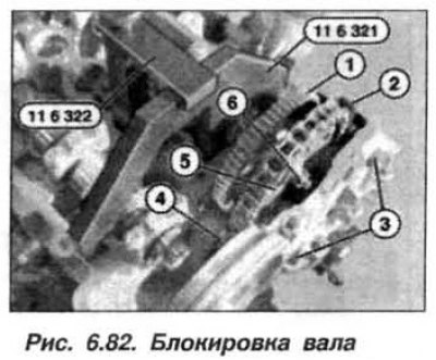
Install the gear (1, Fig. 6.82) and lock the intake camshaft in the position of the first cylinder at TDC at the end of the compression stroke, using tools "11.6.321" and "11.6.322". Insert the tensioner bar (4). Install the sprocket (5). Insert the chain guide (2). Replace the screws (3) and (6). Tighten the new screw (6) by hand. Loosen it by half a turn.
Install the gear (1, Fig. 6.83) and lock the exhaust camshaft in the position of the first cylinder at TDC at the end of the compression stroke, using tools "11.6.321" and "11.6.322".
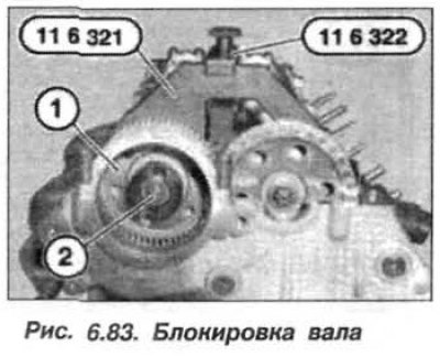
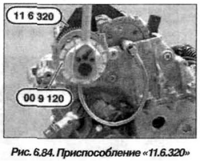
Tighten the new screw (2) by hand and loosen it by half a turn. Remove the "11.3.340" tool and tighten the M6 screw (1, see Fig. 6.75) hydraulic tensioner. Replace the sealing ring, insert the M30x1.0 threaded plug and tighten it to a torque of 70 N·m (7.0 kgf·m). Install the "11.6.320" device (Fig. 6.84) on the exhaust camshaft.
Note: When tightening the sprocket mounting bolts, hold the camshafts from turning using the hexagon.
Using the "00.9.120" tool, tighten the new exhaust camshaft sprocket mounting bolt to 20 N·m (2.0 kgf·m) and tighten it by an additional 50°. Install the "11.6.320" tool on the intake camshaft.
Using tool "00.9.120", tighten the new intake camshaft sprocket mounting bolt to 20 N·m (2.0 kgf·m) and turn it further by 50°. Remove tools "11.6.320" and "11.2.300".
Using the "11.6.480" tool, turn the engine shaft two full turns (720°) in the direction of rotation until the first cylinder reaches the TDC position at the end of the compression stroke (see fig. 6.74).
Check the camshaft adjustment.
Install tools "11.6.321" and "11.6.322" on the camshaft (1, Fig. 6.85) inlet valves. The "11.6.321" device must fit against the cylinder head without any gap.
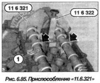
Install the devices "11.6.321" and "11.6.322" on the exhaust camshaft. The device "11.6.321" should fit against the cylinder head without any clearance. Remove all devices and assemble the engine.
(The original is located on the internet portal: BMWMan)