
Attention! When working on the cooling, fuel supply and lubrication systems, it is necessary to protect the generator from contamination by covering it with a thick polyethylene film. Failure to comply with this condition may result in the generator failure.
Installed boost air hoses must be free of grease, dry and clean.
The cylinder head replacement must be carried out in the following order. Prepare the tools "00.2.530", "00.9.120", "11.2.300", "11.3.340", "11.6.321", "11.6.322", "11.6.480", "13.5.020" and "11.6.050" and set the car horizontally. Disconnect the "minus" terminal from the battery and remove the cylinder head cover.
Remove the air conditioner compressor drive belt and the alternator drive belt, cover the alternator with polyethylene film. Drain the coolant and send it for disposal. Remove the vacuum pump.
Remove engine accessory protection panels. Remove heat exchanger hoses (air-to-air radiator) turbocharger and remove the engine. Remove the right engine mount bracket and the exhaust manifold together with the turbocharger.
Secure the engine using the "11.8.040" device on the "00.1.490" assembly stand. It is permissible to use the modified "11.3.350" device. If there is no assembly stand, install the engine on a workbench, remove the vacuum pump and the lower engine shields.
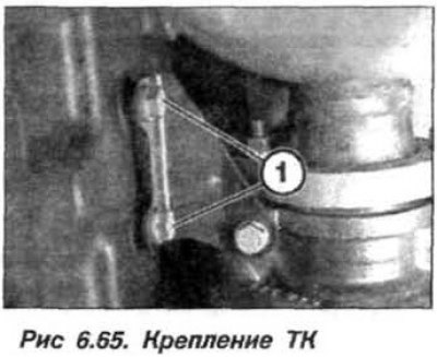
Loosen the TC bracket mounting bolts. Unscrew the bolts (arrows, Fig. 6.65) and disconnect the TC from the exhaust manifold.
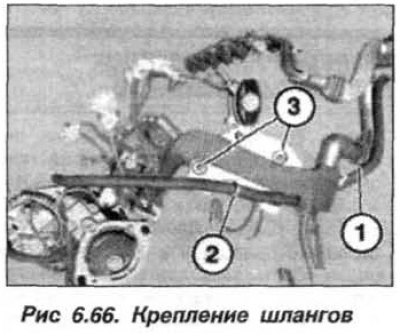
Remove the bolts (3, Fig. 6.66) on the rear of the cylinder head. Remove the cylinder head cover and camshafts.
Attention!
- To avoid damage to the valves when subsequently installing the camshafts, none of the pistons should be at TDC.
- The pusher levers that have been in use are installed only in their original places.
- On the removed cylinder head, the glow plugs protrude above the surface of the head; use stands (blocks).
- For fixtures "11.6.050", manufactured before April 1998, drill to a depth of 20 mm using a 9.5 mm diameter drill.
- Install new cylinder head mounting bolts and cylinder head gaskets each time.
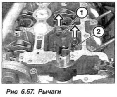
Remove all levers (1, Fig. 6.67) pushers and put them in order. Remove all compensators (2) and put them in order.
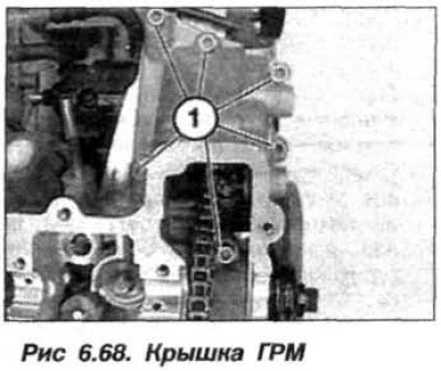
Remove the front screws (1, Fig. 6.68) timing belt cover fastenings.
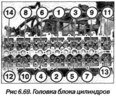
Loosen the cylinder head mounting bolts from the edges to the middle, in the numbering sequence 14 – 1 (Fig. 6.69). Remove the cylinder head and place it on a support, without damaging the protruding glow plugs. If necessary, the glow plugs can be extracted (unscrewed) using the "11.6.050" tool, manufactured after April 1998, or a modified tool – a 9.5 mm drill drilled to a depth of 20 mm.
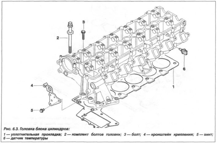
Remove the sealing gasket (1, see Fig. 6.3) cylinder head, paying attention to the marking of its thickness (number of holes).
Installation of the cylinder head should be carried out in the reverse order, taking into account the following features.
Clear the dock (compacted) the surface of the cylinder block and cylinder head from the remains of the seal with a scraper made of hard wood (beech, hornbeam, oak). Seal residue must not enter the oil and coolant supply channels.
Using compressed air, clean all blind threaded holes from traces of oil and coolant.
If no work has been carried out on the engine block on the crank mechanism or pistons that causes changes in the piston crown protrusion, then a new cylinder head gasket with the same thickness marking should be used (number of holes), the same as the previous gasket.
After carrying out work that causes changes in the piston bottom protrusion above the mating surface of the cylinder block, it is necessary to re-determine the thickness of the sealing gasket (see below).
The joints of the timing cover and the cylinder block are sealed using serially glued sealing strips and additional application of sealant in these places is not required. Check the technical condition of the centering sleeve, replace it if necessary. The transitions must be absolutely clean from grease. Always install only a new cylinder head sealing gasket.
Carefully install the cylinder head onto the block. Screw in new cylinder head mounting bolts (washed and lubricated with engine oil) until they are flush with the head. Tighten the new cylinder head bolts in the numbering sequence 1–14 (Fig. 6.69) in five steps:
- 1st step, tighten to 80 Nm (8.0 kgf·m);
- 2nd step, loosen by half a turn (180°);
- 3rd step, tighten to 50 Nm (5.0 kgf·m);
- 4th step, turn to an angle of 90°;
- 5th step, turn another 90° angle.
When turning to a given angle, use the device "00.9.120". Tighten the bolts (1, see Fig. 6.68) timing belt covers.
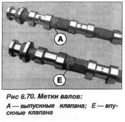
Lubricate the bearing beds and caps of the camshafts with engine oil. Install the hydraulic compensators and pushrod levers in their places. Lay the valve drive camshafts taking into account that the exhaust camshaft has the mark "A" (Fig. 6.70), and the intake camshaft has the mark "E". The marks are applied to the shaft body in the area between the cams of the 1st and 2nd cylinders.
Install the bearing caps. The bearing caps of the exhaust valve drive camshaft have marks - "A1-A7", and the inlet valves - "E1-E7".
Install the TC on the exhaust manifold, replacing the gasket and lubricating the threads with copper-containing paste such as "CRC" or "Molykote-HSC". Tighten the bolts (M10) securing the TC to the exhaust manifold to a torque of 50 N·m (5.0 kgf·m). Tighten the glow plugs to a torque of 18 N·m (1.8 kgf·m). Assemble the engine.