
Remove the oil pump, crankshaft rear oil seal cover, all pistons and front timing cover.
Attention!
- The main bearing caps are bored together with the block and cannot be replaced or repositioned.
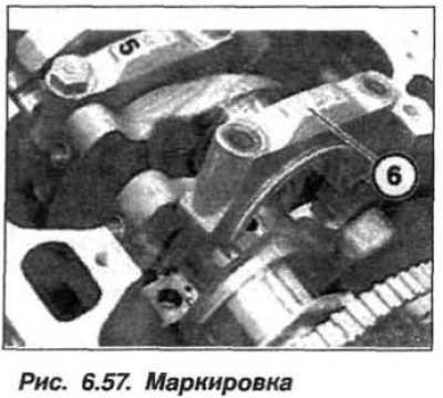
- Bearing caps 1-5 are marked on the exhaust side, bearing caps 6 and 7 are not. Bearing cap 6 is a thrust bearing.
- Lay the removed crankshaft on a stand, excluding contact of the surface with the gear wheel of the speed sensor.
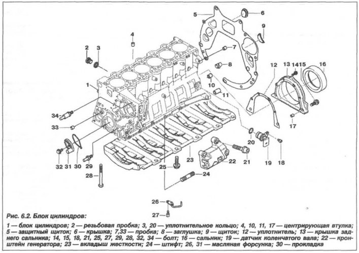
Loosen the bolts (25, 10 pieces, see fig. 6.2), and remove the stiffener (23) crankcase of the cylinder block.
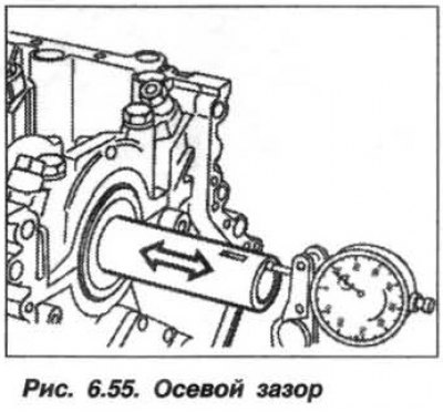
Check crankshaft end play (pic. 6.55). If the axial clearance exceeds the allowable value (0.080–0.234 mm), it is necessary to check the crankshaft and thrust bearing shells. Worn parts must be replaced.
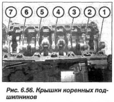
Turn out the bolts of the main bearing caps from the edges to the middle, remove them (1–7, fig. 6.56) and arrange them according to the numbering in «box office» for removable parts. The numbering of the bearing caps starts from the side of the vibration damper.
Remove the crankshaft and carefully place it on a support. Remove the main bearing shells and replace them.
If necessary, loosen the bolts and remove the crankshaft speed sensor gear wheel. When installing the gear wheel, replace the bolts of its fastening with new ones and tighten them:
- M5 (10.9) torque 13 Nm (1.3 kgf·m);
- M5 (8.8) torque 5.5 Nm (0.55 kgf·m).
Remove traces of dirt and oil from blind holes by blowing them with compressed air. Lubricate the main bearing shells with engine oil and place them in the crankcase body and bearing caps.
Lay the crankshaft in the crankcase. Install bearing caps 1 – 7 (bearing 1 on the timing drive side) so that the guide slots of the bearing shell are on the same side. Bearing caps 1 - 5 are marked (pic. 6.57) on the release side. Bearing caps 6 and 7 are not marked. Bearing cap 6 is a thrust bearing. Accurately center the bearing caps.
Replace the main bearing cap bolts with new ones without removing their coating. New mounting bolts (old release) wash in kerosene and lubricate with engine oil. Install the main bearing cap bolts in the following order:
- tighten all the bolts of the main bearing caps from the middle to the edges to a torque of 22 Nm (2.2 kgf·m);
- unscrew the bolts securing the main bearing cap No. 6;
- tap the rear and front ends of the crankshaft with a plastic-headed hammer to expose the thrust bearing;
- tighten the main bearing cap bolts No. 6 to 22 Nm (2.2 kgf·m);
- tighten all the bolts of the main bearing caps from the middle to the edges at an angle of 90°, for which use the tools «11.2.110» or «00.9.120».
Check axial clearance (see fig. 6.55) crankshaft, the nominal value of which should be in the range of 0.080–0.234 mm.
Replace the connecting rod bearing shells and the manual transmission input shaft front bearing, if equipped. Assemble the engine.